


1. Definition: The 45° Mirror That Makes Invisible Lasers ‘Visible’
A beam combiner (also called a beam combiner mirror or beam-combining mirror) is a passive optical component that merges two or more laser beams onto the same optical axis for coaxial propagation. It generates no light and amplifies no light; its core function can be summed up in four words: ‘one transmitted, one reflected’ — one beam is transmitted with high efficiency, the other reflected with high efficiency, so that two beams of different wavelength or polarisation state share the same path for propagation, focusing and processing.
In the laser processing industry, the everyday term ‘beam combiner’ almost always means the red-guide alignment beam combiner: a coated flat plate mounted at 45° in the processing head’s optical path, which transmits the invisible main laser (1064 nm, or 532 nm, 355 nm, 10.6 μm) while reflecting the 635 nm/650 nm visible light from a red alignment diode through 90° into the main path. The red dot the operator sees on the workpiece is thus where the invisible processing laser will strike — the beam combiner makes the invisible laser ‘visible and accurately aimed’, a standard coaxial alignment feature built into every marking, cutting and welding machine.
To understand beam combiners, three closely related concepts must first be distinguished, as these are the ones most often confused in purchasing and technical discussion:
- Beam combiner vs beam splitter: the two share the same principle and their optical paths are reversible, but their design goals are opposite. A splitter divides one beam into two at a set ratio (such as 50:50); a combiner merges two independent sources into one with minimum loss for each. Using a 50:50 splitter as a combiner costs about half the power of each beam, so it can only serve low-power alignment, not a real combining task.
- Beam combiner vs dichroic mirror: a dichroic mirror is a coated component that selects by wavelength — highly transmitting at λ₁ and highly reflecting at λ₂. A red-guide beam combiner is essentially a dichroic mirror; in engineering usage ‘beam combiner’ stresses the purpose of merging two beams, while ‘dichroic mirror’ stresses the film property of wavelength-selective splitting. Combiner plates for multi-wavelength coaxial processing (infrared + green + ultraviolet combined) are series stacks of dichroic mirrors.
- Beam combiner vs polarisation combiner / polarising beam splitter (PBS): a PBS works by polarisation state — p-polarisation (electric field parallel to the plane of incidence) is transmitted, s-polarisation (perpendicular) is reflected. Used in reverse, two orthogonally polarised beams are merged into one — polarisation combining, a core method for multiplying diode laser power and for pump coupling in fibre lasers.
Two further boundaries should be drawn: fibre beam combiners (such as (N+1)×1 pump combiners) are fibre-fusion devices, not mirrors; coherent beam combining (CBC) and spectral beam combining (SBC) are active combining techniques used inside high-power lasers (phase-locked control, gratings/volume Bragg gratings) to synthesise tens of kilowatts, and are a different class of product from the passive mirror-type combiners discussed here.
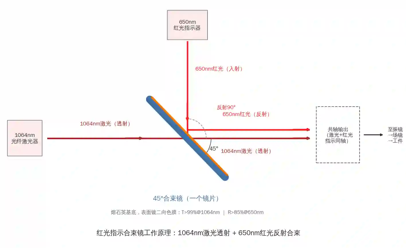
Figure 1 Red-guide combining principle: the invisible 1064 nm fibre laser passes through the 45° combiner while the visible red light from the alignment diode is reflected 90° into the main path, merging the two beams into one coaxial path (schematic drawn by Soar Laser)
2. Physical Principle: How Thin-Film Interference ‘Sculpts’ One-Transmitted-One-Reflected
2.1 Interference mechanism of multilayer dielectric films
The wavelength selectivity of a beam combiner comes from multilayer dielectric films. On a fused silica or K9 substrate, high- and low-index materials (a typical pair is Ta₂O₅/SiO₂ — tantalum pentoxide/silicon dioxide) are deposited alternately in tens of layers, each with an optical thickness of about a quarter wavelength. Light is partly reflected at each film interface, and multiple-beam interference occurs among the reflected waves: when the reflections are in phase constructive interference forms a high-reflection band; when they are out of phase destructive interference keeps that band highly transmitting. By designing the layer count, material combination and thickness profile, the position, width and steepness of the transmission and reflection bands can be precisely ‘sculpted’ onto a single mirror.
Dielectric films have intrinsically very low absorption (down to a few parts in ten thousand), which is the fundamental reason for their orders-of-magnitude advantage over metal films in laser damage resistance. A typical coating specification for a red combiner is: surface 1 (entry face) coated with a main-wavelength anti-reflection film, T>99% @1064 nm; surface 2 coated with the combining film, T>99% @1064 nm and R>85% @650 nm, both specified at 45° incidence (per published specifications from Shanghai Jingsheng Optoelectronics, DXS Optics and other manufacturers).
2.2 Why industrial beam combiners are all mounted at 45°
Beam combiners are generally designed for 45° angle of incidence (AOI) for two reasons. First, geometrically a 45° incidence deflects the reflected light by 90°, allowing the red alignment diode to be mounted perpendicular to the main path — the most compact layout, and the standard arrangement in patented structures for marker combining chambers and cutting-head optics (laser → beam expander → 45° combiner → galvo/focusing lens, with the red diode entering from the perpendicular direction). Second, the spectral characteristics of thin-film interference shift with incidence angle; once a film design is optimised for 45°, it must be used at 45°.
Oblique incidence has one unavoidable physical effect: the p- and s-polarisation spectral responses split apart. For the same film design, s-polarisation reflectance is naturally higher than p-polarisation, and transmittance the reverse. When the incidence angle departs from the design value, the reflection band shifts to shorter wavelengths (blue shift), the bandwidth narrows and the p/s split grows — a 45° plate placed in a near-normal-incidence path can have its operating wavelength fall directly into the transition band, showing up as ‘the mirror looks fine, but the red light dims and combining fails’.
2.3 Wedge angle, ghost images and Fabry–Pérot interference
A combiner plate with two strictly parallel faces forms, between its front and back surfaces, a low-finesse Fabry–Pérot (F-P) cavity: residual reflected light bounces between the two surfaces, and part returns along the original path to the laser as ghost return light; with highly coherent laser light, interference fringes that drift with temperature and angle also appear, causing periodic fluctuation of transmitted power. Making the two surfaces slightly non-parallel — a wedge-shaped combiner — deflects the back-surface reflection out of the main path:
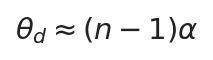
Approximate deflection angle of a wedge plate, where α is the wedge angle and n the refractive index; a 30 arcmin wedge gives a deflection of about 13 arcmin
The common industry standard wedge is 30 arcmin (about 0.5°), enough to break up F-P interference and steer the ghost reflection out of the path; for highly coherent or return-light-sensitive systems, 1°–3° may be used. A wedge plate has a strict mounting orientation: fitting it backwards sends the ghost image back along the original path into the laser and can cause return-light damage, so always install it in the direction marked on the mirror or mount.
In addition, a parallel plate in a converging beam also shifts the focus rearward, just as a protective window does:
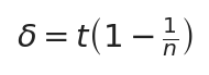
Focal shift of a parallel plate, where t is thickness and n the refractive index; fused silica n≈1.46 gives about 0.95 mm shift for a 3 mm plate
After changing to a combiner of different thickness, the coincidence of the alignment dot and the processing focus must be recalibrated.
2.4 Laser-Induced Damage Threshold (LIDT)
LIDT (Laser-Induced Damage Threshold) is the critical irradiation level below which the film and substrate suffer no irreversible damage (ablation, film delamination, cracking) under specified conditions, tested to the ISO 21254 series. Continuous-wave and pulsed lasers are checked with two different units:
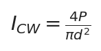
Average power density for CW lasers, where P is laser power and d the spot diameter at the mirror, in W/cm²
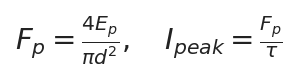
Pulse laser fluence Fp (J/cm²) and peak power density, where Ep is single-pulse energy and τ the pulse duration
Three iron rules govern combiner LIDT: ① it varies sharply with wavelength and pulse duration and must not be transferred across conditions — referencing published dichroic film data from LASER COMPONENTS, typical thresholds are about 10–30 J/cm² at 1064 nm/10 ns, about 5 J/cm² at 532 nm, about 5 J/cm² at 355 nm UV, and on the order of 1 MW/cm² for CW; ② film thresholds are usually lower than those of the bare substrate, with film absorption and surface defects such as scratches and pits acting as damage initiation sites; ③ LIDT is measured in a clean laboratory and is not the permissible on-site power density — contamination causes a steep drop in effective threshold, so engineering practice requires a several-fold margin based on wavelength, pulse duration, spot size and contamination level.
3. Structure and Classification
3.1 By combining mechanism: wavelength, polarisation and angular combining
① Wavelength combining (dichroic type, the overwhelming industrial mainstream): wavelength is the selection dimension; the film transmits the main wavelength and reflects the alignment/auxiliary wavelength, independent of polarisation state and placing no demand on source polarisation purity. It is the most robust method for red-guide alignment in processing heads and for multi-wavelength coaxial systems. Typical specifications: 1064 nm high transmission + 650 nm high reflection (fibre marking/cutting), 532 nm high transmission + 650 nm high reflection (green processing), 355 nm high transmission + visible high reflection (UV processing), 10.6 μm high transmission + 650 nm high reflection (CO₂ processing, ZnSe substrate).
For multiple coaxial wavelengths, two or more dichroic mirrors can be stacked in series to combine stage by stage — for example 1064 nm infrared, 532 nm green and 355 nm ultraviolet sharing one field lens, allowing process switching of ‘infrared marking + green welding + UV precision machining’ at a single station:
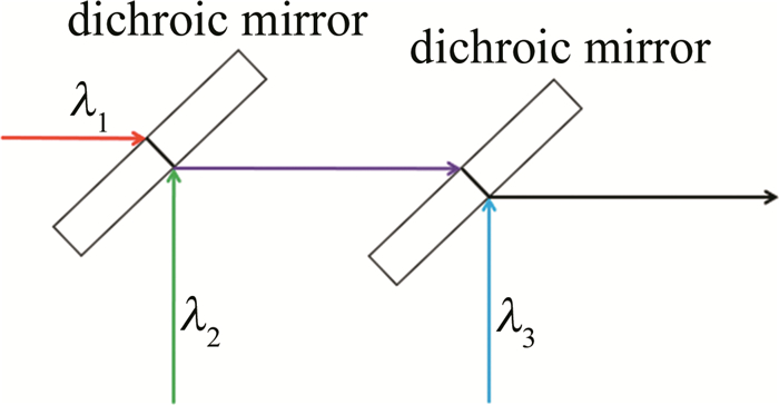
Figure 2 Series dichroic combining: three wavelengths λ₁, λ₂, λ₃ are merged stage by stage through two 45° dichroic mirrors into a coaxial output (image source: technical material from Laser Technology journal)
The key spectral concept in wavelength combining is the transition band: the interval between the transmission and reflection bands. The smaller the gap between the two wavelengths, the narrower the transition band required, the more layers needed, the harder the process and the higher the cost. Red (650 nm) and infrared (1064 nm) are separated by more than 400 nm, so the film design is relaxed — which is why red combiner plates are inexpensive and durable.
② Polarisation combining (PBS type): polarisation state is the selection dimension. Two lasers of the same wavelength but orthogonal polarisation states — one p-polarised transmitted, one s-polarised reflected through 90° — are merged into one beam containing two polarisation components:

Polarisation combining efficiency, where Tp is p-transmittance, Rs is s-reflectance and fp/fs are the power fractions of the two paths; a quality PBS has Tp>95% and Rs>99.5%
The engineering value of polarisation combining is power multiplication at preserved brightness: the powers of two beams add without enlarging the spot aperture, and the beam parameter product (BPP) degrades only slightly. It is the basis for diode laser bar combining, pump coupling in fibre lasers and polarisation multiplexing in double-clad fibre. Its limits are that only two beams can be combined and both paths need high polarisation purity with matched power and spot; a quality polarising beam-splitter cube (such as the Thorlabs high-power PBS25 series) reaches an extinction ratio Tp:Ts above 2000:1, with p-transmittance about 95% and s-reflectance about 99.5%.
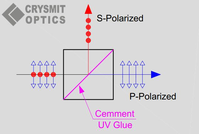
Figure 3 Polarising beam-splitter cube (PBS) principle: p-polarisation transmitted, s-polarisation reflected through 90°; reversing the path gives polarisation combining (image source: CRYSMIT OPTICS)
③ Angular combining (spatial beam addition): the beams enter the same aperture at small relative angles, are brought together spatially by a partially reflecting surface, and the output retains a residual angle that converges by far-field superposition. It is structurally the simplest and insensitive to both wavelength and polarisation, but the result is not strictly coaxial and each added path introduces another transmission/reflection loss; it is used mainly for incoherent power addition of multimode lasers. Note that angular combining relies on spatial arrangement, not on a misunderstanding of thin-film angular effects as ‘the same wavelength at different angles alternately transmitting and reflecting’.
Beyond mirror-type combiners, the high-power laser field has two active combining techniques (per RP Photonics Encyclopedia): coherent beam combining (CBC) requires mutually coherent, phase-locked sources combined by diffractive optical elements into a single beam, giving the highest brightness at the cost of system complexity; spectral beam combining (SBC) uses a diffraction grating or volume Bragg grating (VBG) to diffract several mutually incoherent beams of slightly different wavelength into the same direction, needing no phase locking, with good stability and with a single emitter failure reducing only power, not beam quality — the mainstream route for hundred-kilowatt-class diode/fibre laser synthesis. The gratings and phase controllers these use are outside the scope of passive combiner mirrors, but are often mentioned alongside them in selection discussions:
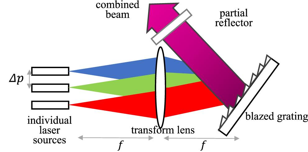
Figure 4 Spectral beam combining (SBC) principle: sources of different wavelengths enter a blazed grating through a transform lens, and the angular dispersion of the grating makes the beams overlap in one output direction (image source: Frontiers in Physics (open access))
3.2 By coating type: dielectric films and metal films
| Item | Multilayer dielectric-film combiner | Metal-film combiner |
|---|---|---|
| Working principle | Interference of multilayer Ta₂O₅/SiO₂ films, selective transmission/reflection | Partial reflection by a metal layer of chromium, aluminium or silver (e.g. Polka Dot array) |
| Absorption loss | Very low (order of a few parts in ten thousand) | Several percent, with noticeable heating |
| Spectral characteristics | Selective, relatively narrow band, angle-sensitive | Broad flat spectrum, polarisation-insensitive, angle-insensitive |
| Damage threshold | High (up to 10–30 J/cm² at 1064 nm/10 ns) | Low; will burn at high power |
| Typical use | Industrial laser processing, high-power combining (the only realistic choice) | Low-power alignment, broadband measurement, laboratory splitting |
3.3 By form: flat-plate and wedge
A flat plate has two parallel faces, the simplest structure and lowest cost, and is the most common form of red combiner in marking machines (red power is only milliwatts, so return light is minor); a wedge has a wedge angle of 30 arcmin to a few degrees between its faces, suppressing F-P interference and ghost return light, for highly coherent, high-power and precision-measurement paths. Commercial combiners commonly come in diameters Φ12.7 mm (1/2 inch), Φ20 mm, Φ25 mm, Φ25.4 mm (1 inch), Φ30 mm, Φ38.1 mm, with thickness 1.5–3 mm; diameter tolerance +0/−0.1 mm and thickness tolerance ±0.25 mm are typical industry levels.
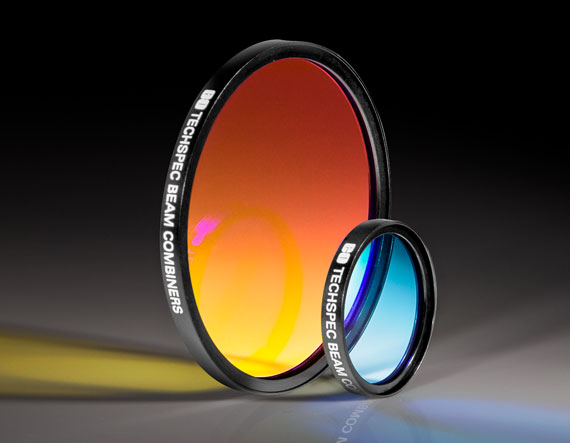
Figure 5 An industrial dichroic laser beam combiner: precision-sealed in a metal ring, the coloured reflection on the optical face is the interference signature of the multilayer dielectric film (image source: Edmund Optics)
4. Key Technical Parameters and Their Selection Significance
| Parameter | Typical specification/description | Selection significance |
|---|---|---|
| Centre wavelength / transmission-reflection band | E.g. 1064 nm high-transmission band 1060–1090 nm, 650 nm high-reflection band; transition band between the two | The actual laser wavelength (including thermal drift and linewidth) must lie inside the guaranteed band; the gap between the two wavelengths sets film difficulty and cost |
| Transmittance T / reflectance R | Main wavelength T>99%; alignment light R>85% (red combiner); polarisation combining Tp>95%, Rs>99.5% | T directly sets main-path loss: on a 12 kW system every 1% of transmittance is 120 W of loss and heat; R sets red-light brightness |
| Angle of incidence AOI | 45° standard for industrial combiners; all specifications given at 45° | Angle is an optical, not a mechanical, parameter: departing from the design angle shifts the reflection band blue, splits p/s and sharply cuts combining efficiency |
| Polarisation characteristic P/S | At oblique incidence p and s spectra necessarily separate; for polarisation components check the extinction ratio (e.g. Tp:Ts>2000:1) | For non-polarised paths use average specifications; for polarisation combining or paths containing isolators and waveplates, select by p/s component |
| Damage threshold LIDT | About 10–30 J/cm² at 1064 nm/10 ns; about 5 J/cm² at 532/355 nm; order of MW/cm² CW (ISO 21254) | Check CW in W/cm² and pulsed in J/cm² with pulse duration stated; quoted values must include test conditions, with a several-fold margin |
| Substrate material | Fused silica JGS1 (UV to near-IR, low expansion 0.5×10⁻⁶/K); K9/BK7 (low-cost visible to near-IR); ZnSe (10.6 μm CO₂) | UV and above-kW use fused silica; CO₂ must use ZnSe (fused silica strongly absorbs 10.6 μm and can crack if mis-selected); low-power visible can use K9 |
| Surface figure / surface quality | Figure λ/4–λ/10 @633 nm; surface 40-20 or 20-10 scratch-dig | Figure sets transmitted wavefront distortion, affecting M² and focused spot; scratches and digs add scatter and lower real LIDT |
| Outline dimensions | Φ12.7–Φ50.8 mm, thickness 1.5–3 mm; flat or wedge | Must match mount aperture and thickness slot; note mounting orientation for wedges |
5. Typical Applications and Selection Guidance
① Red-guide alignment for fibre laser marking/cutting/welding (largest volume). The optical order is: laser (QBH output) → beam expander → 45° combiner → galvo (marking) or collimation/focusing group (cutting/welding) → field lens/protective window → workpiece; the red alignment diode enters the combiner from the perpendicular direction. Selection: for 1064 nm choose an H-K9L/JGS1 substrate combiner (T>99% @1064, R>85% @650, 45°), commonly Φ20×2 mm or Φ25×3 mm; for above-kW cutting/welding JGS1 fused silica is advised. After replacement, recalibrate the coincidence of the red dot and the focus.
② Red-guide alignment for CO₂ laser engraving and cutting. The 10.6 μm laser is invisible and strongly absorbed by fused silica, so the combiner must use a ZnSe substrate (CVD zinc selenide, 10.6 μm high transmission + 650 nm high reflection), commonly Φ20×2 mm or Φ25.4×2/3 mm; the complete mount kit is supplied with the red diode and reflector. ZnSe costs far more than silica wafers, and its cutting/polishing dust is hazardous, so discarded mirrors must be disposed of per regulations.
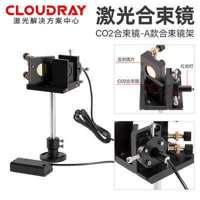
Figure 6 A CO₂ laser combiner mount assembly: ZnSe combiner (pale yellow mirror) + red alignment diode + reflector, with the red light coaxial with the invisible 10.6 μm laser (image source: Cloudray)
③ Alignment combining for green/UV processing. 532 nm green and 355 nm UV markers use combiners highly transmitting at the matching wavelength (532T/650R, 355T/visible R); the UV band requires a fused silica substrate, and the 355 nm film LIDT is markedly lower than at 1064 nm (about 5 J/cm² @10 ns), so picosecond/femtosecond UV systems especially need ample threshold margin.
④ Multi-wavelength coaxial processing and multicolour research paths. 1064/532/355 nm sharing one field lens, pump-probe experiments, RGB laser display (red, green and blue combined into white through two dichroic mirrors), fluorescence excitation and so on use series dichroic combiners. Selection centres on matching the wavelength gaps and transition bands of each channel and keeping inter-channel isolation (leakage in the reflection band / residual reflection in the transmission band) low enough.
⑤ Polarisation combining and pump coupling. Diode bar power multiplication, fibre laser pump source synthesis and double-clad fibre polarisation multiplexing use polarising beam-splitter cubes / thin-film polarisers in reverse. Selection looks at extinction ratio, Tp/Rs efficiency and LIDT; the combined output is mixed polarisation, so if a single linear polarisation is needed downstream, a waveplate must be added for conditioning.
Six-step selection method (can be followed directly for purchasing and maintenance):
- Fix the wavelength: main laser wavelength (1064/532/355/10.6 μm) + alignment wavelength (635/650/532 nm), listing all channels for multi-wavelength systems;
- Fix the substrate: JGS1 fused silica for UV/above-kW, ZnSe for CO₂, K9 acceptable for low-power visible;
- Fix the film specification: main-wavelength T, alignment-light R, 45° incidence, whether polarisation-sensitive; request measured spectral curves with the incidence angle stated from the manufacturer;
- Fix the dimensions: check diameter × thickness against the mount slot (Φ20×2, Φ25×3 most common), and confirm whether it is a wedge and its mounting orientation;
- Fix the threshold: compute power/energy density from actual power or energy, spot diameter and pulse duration, then compare with LIDT data that include test conditions and leave a several-fold margin;
- Fix the acceptance test: on arrival inspect the coated face for scratches and digs under light; after installation verify red-light brightness and coaxiality at low power, then ramp to operating power.
6. Handling, Maintenance and Common Misconceptions
Maintenance essentials: the cleaning discipline for a combiner is the same as for all laser optics — first blow off loose dust with nitrogen or clean compressed air, never wipe dry; wipe gently with a lint-free swab dipped in optical-grade anhydrous alcohol, from centre outward in one direction, using a fresh swab per pass; replace the mirror if light inspection shows haze or scratches. A useful field rule of thumb: a red dot that grows dim, fuzzy or faint is often the first sign of combiner contamination or film degradation — the alignment light uses only the reflection path and is only milliwatts, so film contamination affects its brightness far more visibly than the main laser; when the red light looks abnormal, check the combiner first. At installation the 45° angle must be precise (an angular error also shifts the red dot, causing misalignment with the processing focus); after changing a combiner or its thickness, recalibrate the red-dot/focus coincidence and include it in routine checks. Store spare mirrors in constant temperature and dryness in their original packaging — prolonged humidity causes spectral drift and film delamination.
Common misconceptions:
| Misconception | Correct understanding |
|---|---|
| ‘A beam combiner is just a splitter used backwards’ | The principle is shared and the path reversible, but the film design is optimised in opposite directions: a combiner seeks double-high (high T in the transmission band + high R in the reflection band), while a 50:50 splitter seeks a fixed split. Using a splitter to combine loses about half of each beam’s power, causing severe heating at high power; only low-power alignment can get by |
| ‘Higher transmission means higher power tolerance (high T = high LIDT)’ | T/R is a spectral-efficiency metric, LIDT a thermodynamic one; they are not necessarily linked. A metal film can also give a flat split curve but absorbs several times more and will burn at high power; power tolerance depends only on LIDT data with stated test conditions |
| ‘A degree or two off at 45° does not matter, just fit it’ | Film spectra are a function of incidence angle: an angular error shifts the reflection band blue, narrows bandwidth and splits p/s, so the working wavelength may fall into the transition band — the red light dims and combining fails while the mirror ‘looks fine’. Check the angle first whenever transmission/reflection looks wrong |
| ‘Swap in a quartz combiner on CO₂ too, it is cheaper’ | Fused silica strongly absorbs 10.6 μm and will heat and crack at high power; a CO₂ combiner must use ZnSe (GaAs also works but does not transmit visible light, so it cannot provide red-guide alignment) |
| ‘A dim red light means the red diode is broken’ | Check the combiner first: film contamination, ablation or an off-angle mount all sharply cut red reflection efficiency; combiner contamination progresses at a similar rate to a protective window, and continuing to use it dirty goes from dim red to a burned-through film |
| ‘A wedge plate has no front or back, any orientation fits’ | A wedge fitted backwards sends the back-surface ghost image along the original path into the laser and can cause return-light damage at high power; install it in the direction marked on the mirror or mount |
| ‘Beam combiners, dichroic mirrors and polarisation combiners are the same thing, buy any’ | The selection dimensions differ: wavelength combining looks at wavelength gap and transition band, polarisation combining at extinction ratio and Tp/Rs, red-guide alignment at main-wavelength T + red R; quoting the wrong parameter buys the wrong film and fails on installation |
The reversibility of combiner and splitter paths is shown below: the same dichroic element, with light travelling backwards, changes from ‘combining’ to ‘splitting’ — which is why dichroic mirror product pages often carry both names, Beam Combiner and Beamsplitter.
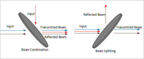
Figure 7 Combining (Beam Combination) and splitting (Beam Splitting) are inverse processes (image source: Lbtek Optics)
7. Notes and Industry Background
The name ‘beam combiner’ as a laser-processing accessory became fixed as red alignment diodes spread on domestic marking machines — early YAG markers used invisible 1064 nm light and were hard to focus, and the red-pointer + 45° combiner coaxial alignment scheme became the industry standard for its simple structure and low cost, making the combiner a stock item in marking and cutting machine consumables lists. In coating process, domestic combiners generally use electron-beam evaporation or ion-beam sputtering (IBS) hard films; the latter are dense, wear-resistant, cleanable and resistant to humidity and UV, belonging to the same technical route as the industrial dichroic mirrors of international makers such as Thorlabs and Edmund Optics. Where higher integration is needed, there are modules combining red alignment, combining and collimation/expansion in one; the fibre-device form, the ‘fibre beam combiner’ (pump or power combiner), is a fused-taper fibre product — take care to distinguish it from mirror-type combiners when purchasing.
8. References
- RP Photonics Encyclopedia, Beam Combining (classification and principles of coherent/spectral/polarisation combining)
- RP Photonics Encyclopedia, Spectral Beam Combining (comparison of combining elements: gratings, VBGs, dichroic mirrors)
- Thorlabs, Dichroic Mirrors/Beamsplitters (45° selection of dichroic mirrors/combiners and combining-path application notes)
- Thorlabs, High-Power Polarizing Beamsplitter Cubes (high-power polarising split/combine cubes: extinction ratio 2000:1, LIDT data)
- LASER COMPONENTS, Dichroic Mirror Coatings data sheet (T/R specifications of HR1064HT532-type films and typical 10 ns LIDT values)
- Shanghai Jingsheng Optoelectronics, laser beam combiner product specifications (industry specs: 1064 nm T>99%, 650 nm R>85%, 45° incidence)
- Daheng Optics, beam combiner product manual (PDF) (specification series for ZnSe/H-K9L/JGS1 combiners at various wavelengths)
- Wavelength Opto-Electronic, BC/BCZ Series 45° Beam Combiner (BK7/fused silica/ZnSe combiners, 355 nm–10.6 μm transmitting IR and reflecting visible alignment light)
📚 Further reading
- Dichroic mirror encyclopedia: long-pass/short-pass dichroic mirror principles, specifications and laser combining selection (the film essence of a red combiner is a dichroic mirror)
- Laser protective window encyclopedia: selection and materials for protection windows at every station in cutting/welding/galvo/field-lens paths
- Field lens (F-Theta flat-field lens) encyclopedia: selection of the core focusing element for marking
- Laser beam expander encyclopedia: principles, classification, selection and use
- Laser collimator encyclopedia: collimation principles, lens-group structure and industrial selection
- Achromatic F-Theta lens encyclopedia: multi-wavelength confocal F-Theta field lens selection
- Polarisation rotator (Faraday rotator / half-wave plate / liquid-crystal three routes, principles and selection)
🔧 Related products and services
Soar Laser supplies the full range of laser-processing optical components and selection support: red-guide beam combiners (fused-silica based for 1064/532/355 nm, ZnSe based for 10.6 μm CO₂, Φ20/Φ25/Φ25.4/Φ30 mm in stock), protective windows, focusing lenses, collimators, field lenses and beam expanders, compatible with mainstream cutting/welding/marking heads from RayTools, Jiaqiang, Wanshengxing, Hongshan and Han’s Laser; polarising beam-splitter cubes, dichroic mirrors, waveplates and other scientific and industrial polarisation components can be supplied to order by wavelength, incidence angle and LIDT. All mirrors can be checked against the head model and specification; bulk purchases and OEM supply are welcome.
Selection hotline (WeChat same number): 15927220467; tell us the equipment model or head nameplate and we will check the combiner wavelength, substrate, dimensions and film orientation for you.
Leave a Reply