


This guide is published by Soar Laser for engineers and technical buyers who assemble a CO2 laser marking machine on their own. The machine configuration covered here is: a Coherent C30A 30 W air-cooled RF CO2 laser source + a BJJCZ FBLI-B-LV7A digital marking card (referred to as the FBLI-B-LV7 series throughout its manual) + Mean Well LRS-600-48 / RS-15-5 power supplies + an XY2-100 protocol digital galvo scanner + Sino Galvo F-Theta lens / beam expander / beam combiner. All wiring definitions follow two official manuals: the Coherent “New C-Series Laser User Guide” and the BJJCZ “FBLI-B-LV7 Card Manual (V4.0.9, 2025-02-12)”.
If you are assembling a fiber laser marking machine instead, see our previous article: Fiber Laser Marking Machine Assembly Guide. This guide follows the same structure, but every interface and parameter has been re-verified for CO2 RF laser sources.
1. Complete Parts List
| Component | Brand and Model | Key Specifications | Function |
|---|---|---|---|
| CO2 laser source | Coherent C30A (30 W air-cooled RF) | 30 W, 10.55–10.63 μm, output spot 1.8±0.2 mm, 48 VDC supply, RJ45 control port | Marking light source; RF board with onboard air cooling, no external water chiller needed |
| Marking card | BJJCZ FBLI-B-LV7A | J1 digital galvo port / J3 multiplexed laser control port / J4 power and IO port | The brain of the machine: generates galvo signals and laser PWM; connects to the PC via USB |
| Laser power supply | Mean Well LRS-600-48 | 48 V / 12.5 A / 600 W (typical draw 11.5 A; margin is tight, see 6.1) | Powers the C30A |
| Marking card power supply | Mean Well RS-15-5 | 5 V / 3 A / 15 W | Supplies 5 V to the marking card via J4 |
| Digital galvo scanner | XY2-100 protocol digital galvo scanner | X/Y dual mirrors, differential signals, requires its own power supply | Deflects the beam to perform planar scanning |
| F-Theta lens | Sino Galvo SL1-10.6-110-150Z-LP F-Theta lens | Work area 110×110 mm, focal length 150 mm | Focuses the beam deflected by the galvo onto the workpiece plane |
| Beam expander | Sino Galvo BEX-10.6-4X-LP beam expander | 4× expansion, 1.8 mm → 7.2 mm | Expands the beam and narrows its divergence, improving focused spot quality |
| Beam combiner | Sino Galvo BCZ-10.6T/650R-D20-T2-LP beam combiner | Transmits 10.6 μm and reflects 650 nm red light; φ20×2 mm bare substrate (requires a 20 mm optic mount) | Makes the red pointer beam coaxial with the laser beam |
| Red pointer | External 650 nm module | Control: J3 Pin22 (REDPT) preferred / J4 Pin2 (OUT4) backup | Marking preview and positioning |
| Industrial PC | Any PC (EZCAD2/EZCAD3) | Connects to the marking card via USB | Runs the marking software |
Note: choose the galvo power supply according to the rating printed on your galvo driver board
- The digital galvo scanner is powered by its driver board, typically a ±15 V dual-rail linear supply (±12 V / ±24 V variants also exist). Follow the marking on the galvo kit in hand; when purchasing the galvo, confirm the matching power supply directly with the supplier. In the diagrams of this guide it is labeled generically as the “galvo power supply” without specifying a model.
2. System Layout
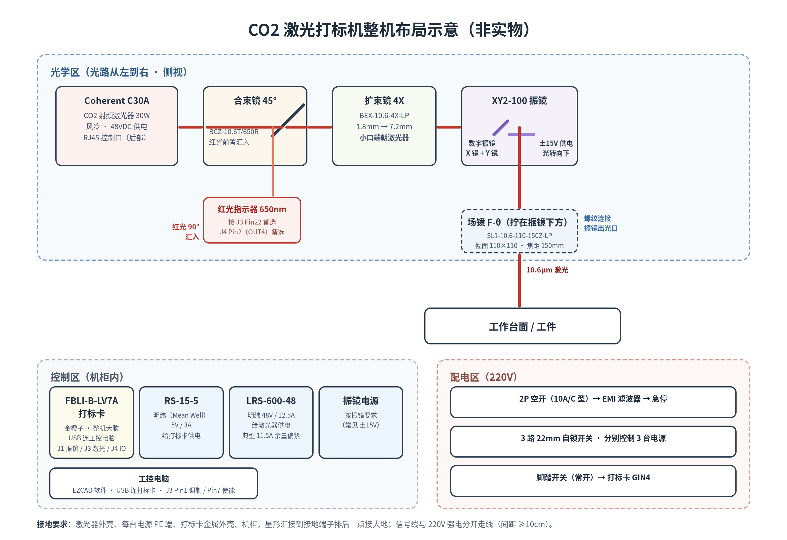
Fix the layout in your head before wiring: in the optical zone, from left to right, the beam travels laser source → beam combiner → beam expander → galvo scanner → F-Theta lens (the red pointer joins the main optical path via the beam combiner before the beam expander, so the red beam is expanded together with the laser; see Section 11 for why), and finally lands on the worktable. The control zone holds the marking card and the three power supplies; the power distribution zone handles the 220 V input and protection. Mount all components securely inside the cabinet and leave at least 10 cm of clearance around the laser source for heat dissipation (required by the C-series manual; air cooling is critical to CO2 laser lifetime).
3. Tools and Materials
- Wire strippers, crimping pliers, RJ45 crimp tool + shielded RJ45 plugs and 8-core shielded network cable
- DB25 (J3) and DB15 (J1) solder-type connectors or crimp terminals, plus metal-hood DB25/DB15 cable shells
- 2.5 mm² red/black power wire (48 V main loop), 0.75–1 mm² signal wire, 2.5 mm² yellow-green grounding wire
- Digital multimeter (mandatory), heat-shrink tubing, cable ties, spiral wrap sleeve
- 2-pole MCB (10 A, Type C), EMI filter, red emergency stop button, 22 mm latching switches ×3
- Oscilloscope (recommended ≥50 MHz with 10:1 probes, to verify PWM and LASER OK timing)
- Laser power meter (optional, e.g., Ophir Nova + sensor head, for acceptance testing of actual output power; see the Ophir power meter selector for selection)
4. 220 V Power Distribution
Distribution principle: main protection → filtering → emergency stop → independent branch control. Three latching switches separately control the laser power supply, the galvo power supply, and the marking card power supply. The benefit: during commissioning you can power only the marking card and the galvo while keeping the laser de-energized — safe and convenient for troubleshooting.
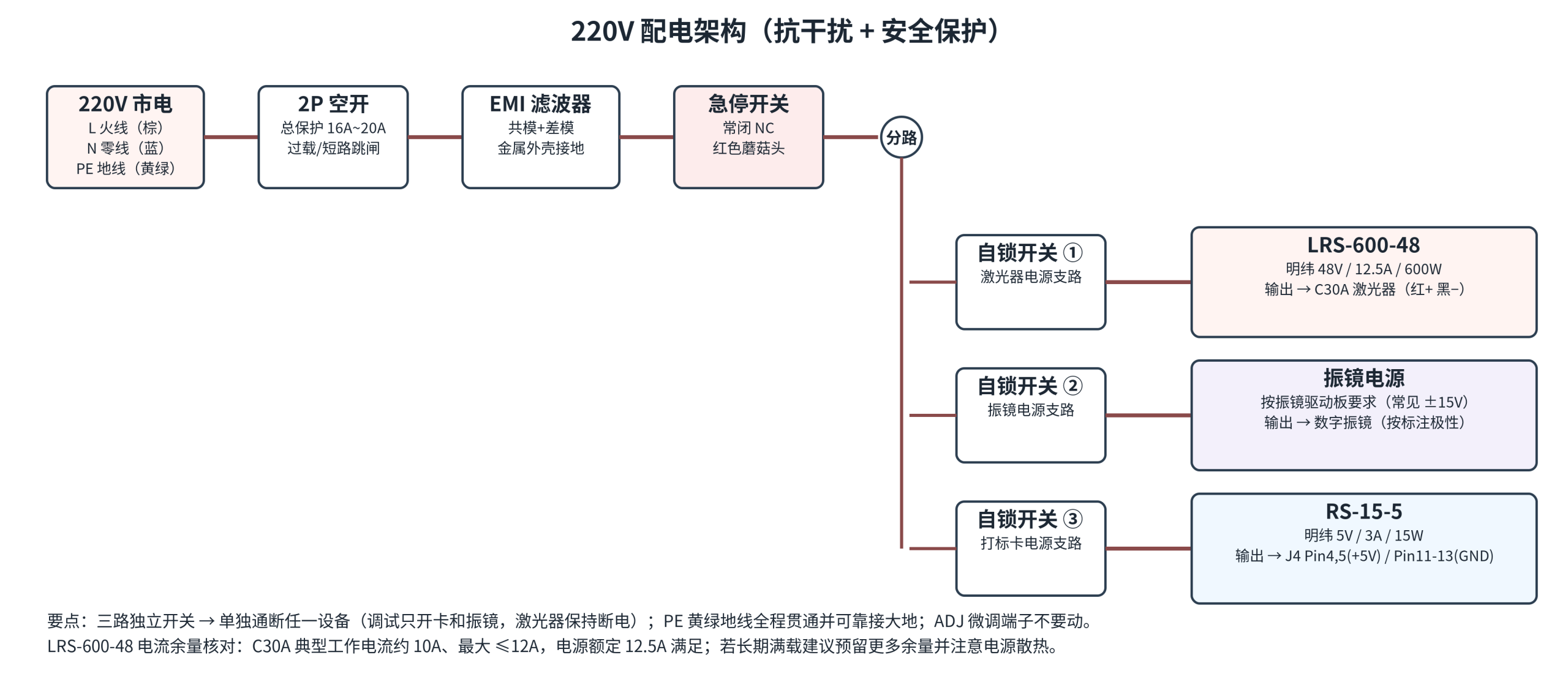
- Feed the 220 V mains into a 2-pole MCB (16–20 A, main protection).
- Connect the MCB output to the EMI filter input; the metal housing of the filter must be earthed (to suppress RF interference — both the CO2 RF laser source and the digital galvo are interference sources).
- Connect the filter output to the emergency stop switch (normally closed NC, red mushroom head, mounted in a prominent position on the cabinet panel).
- Split the emergency stop output into three branches, each going through one 22 mm latching switch to the 220 V input of the LRS-600-48, the galvo power supply, and the RS-15-5 respectively.
- Connect the PE terminal (housing earth terminal) of each switching power supply to the cabinet grounding terminal block with 2.5 mm² yellow-green wire (star topology), and earth the block at a single point; do not daisy-chain the PE terminals end to end. The ADJ trim terminals of Mean Well supplies are calibrated at the factory — do not touch them.
5. Overall Wiring Overview
The diagram below shows all wiring at a glance. Get the overall picture first, then follow each section in detail:
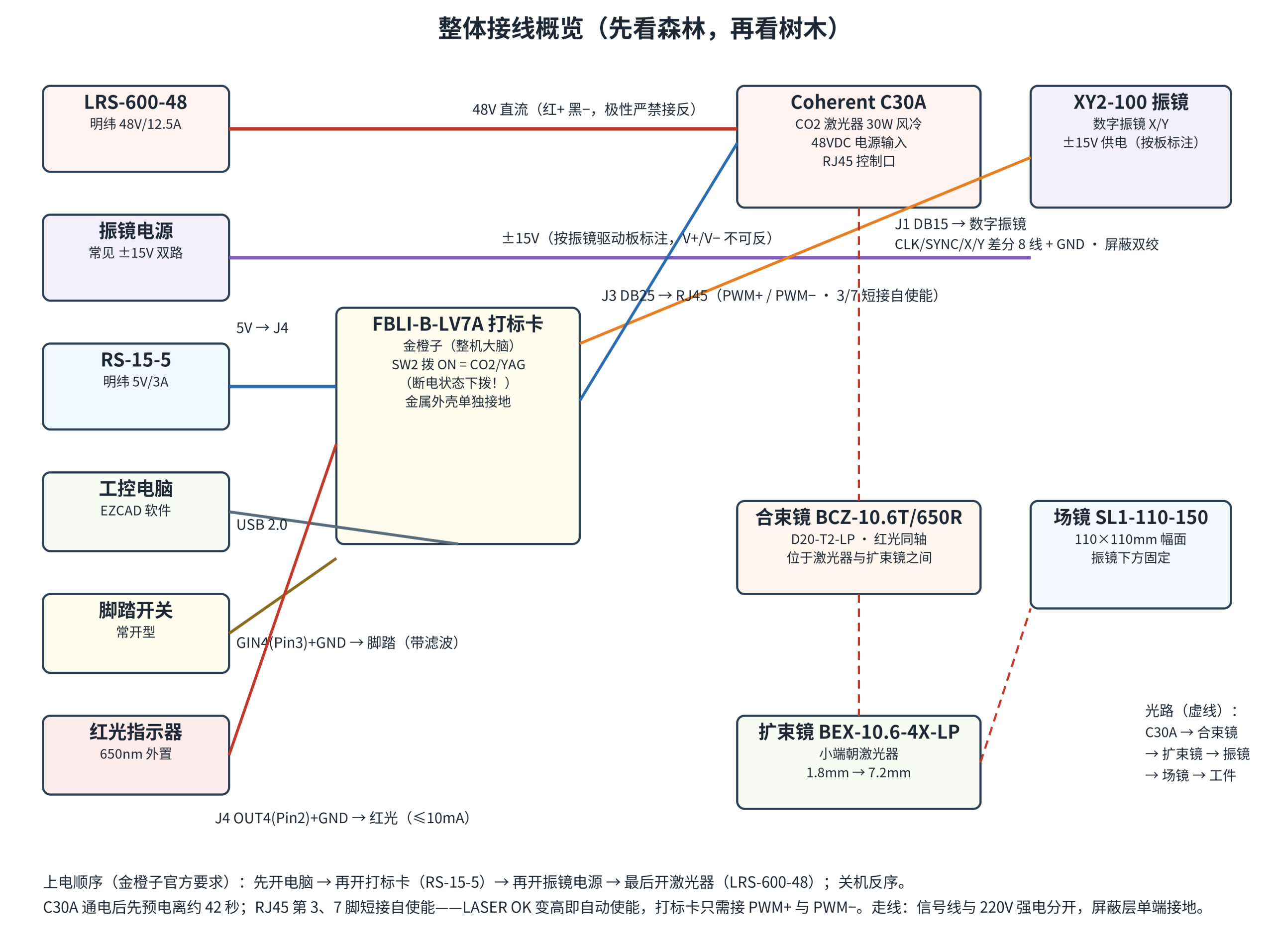
Power-on sequence (required by BJJCZ — follow strictly)
- Startup: power on the PC first → then the marking card supply (RS-15-5) → then the galvo power supply → finally the laser power supply (LRS-600-48).
- Shutdown in reverse order: switch off the laser power supply first, then the galvo, the marking card, and the PC in sequence.
- Reason: if the laser is powered before the marking card is ready, an abnormal software trigger could cause uncontrolled lasing.
6. DC-Side Power Wiring
6.1 LRS-600-48 → C30A laser source (48 V)
- With the laser source not yet connected, power on the LRS-600-48 and measure the output with a multimeter: 48 V±2% (47.0–49.0 V passes).
- After powering off, wire it up: V+ → C30A power input positive (red wire), V− → negative (black wire). Reverse polarity will burn the RF board of the laser source; double-check after wiring.
- C30A supply requirements: 48 VDC±2%, ripple P-P below 1% (C-series manual Table 1.2.1). Typical operating current is 11.5 A with peaks up to 35 A (within 1 ms, Table 3.2.1); the LRS-600-48 is rated 12.5 A, leaving only about 8.7% margin over the typical current — long full-power marking runs can easily trip overcurrent protection (OCP). Consider upgrading to a 15 A or higher supply, or, as the manual suggests, add 2200–4700 μF low-ESR electrolytic capacitors (with a 0.1 μF ceramic capacitor) in parallel at the supply output to absorb peak current; after installation, verify with an oscilloscope that ripple is below 480 mV. Always insert a 15–20 A fuse in series on the supply output side before the laser source.
- Keep the power wires as short and thick as possible (4 mm² recommended for the 48 V main loop; a 1 m run drops about 0.3 V) and crimp the terminals firmly.
6.2 RS-15-5 → marking card J4 (5 V)
| RS-15-5 output | Marking card J4 pin | Note |
|---|---|---|
| +5V | Pin4, Pin5 (VCC) | Wire both pins to reduce voltage drop |
| GND | Pin11, Pin12, Pin13 (GNDIN) | Wire all three pins |
The measured output should be between 5 and 5.2 V (the manual recommends 5 V/3 A). With only the marking card powered, the card’s indicator lighting up normally confirms the supply is good.
6.3 Galvo power supply → galvo data cable → galvo scanner
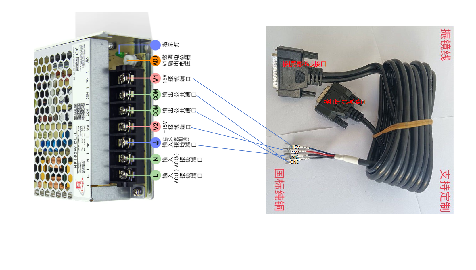
Connect galvo power supply V1 to the +15 V wire of the galvo data cable, V2 to the −15 V wire, and COM to the GND wire; connect the ground lead of the galvo power supply and the ground wire of the galvo data cable together to earth. Plug the 25-core DB end of the galvo data cable into the DB25 port on the galvo head housing, and the 15-core DB end into the J1 port of the BJJCZ marking card (labeled “TO scanhead”).
7. J1 Digital Galvo Wiring (DB15) Pinout
The FBLI-B-LV7 outputs XY2-100 digital galvo signals directly from J1; simply mate it with the DB15 port of the galvo driver board. Pinout (per the BJJCZ manual):
| J1 pin | Signal | J1 pin | Signal |
|---|---|---|---|
| Pin1 | CLK− (clock−) | Pin9 | CLK+ (clock+) |
| Pin2 | SYNC− (sync−) | Pin10 | SYNC+ (sync+) |
| Pin3 | X Channel− | Pin11 | X Channel+ |
| Pin4 | Y Channel− | Pin12 | Y Channel+ |
| Pin5/6/7/13/14 | Reserved (leave unconnected) | Pin8/15 | GND |
- You must use shielded twisted-pair cable (pin-to-pin correspondence between the two mating connectors); differential signals rely on it for interference immunity.
- Ground the shield at one end only (to GND); grounding both ends creates a ground loop.
- After power-on the galvo performs a homing motion with a light click — this is normal.
8. J3 → C30A Laser Wiring: RJ45 Pinout and Enable Configuration (Core)
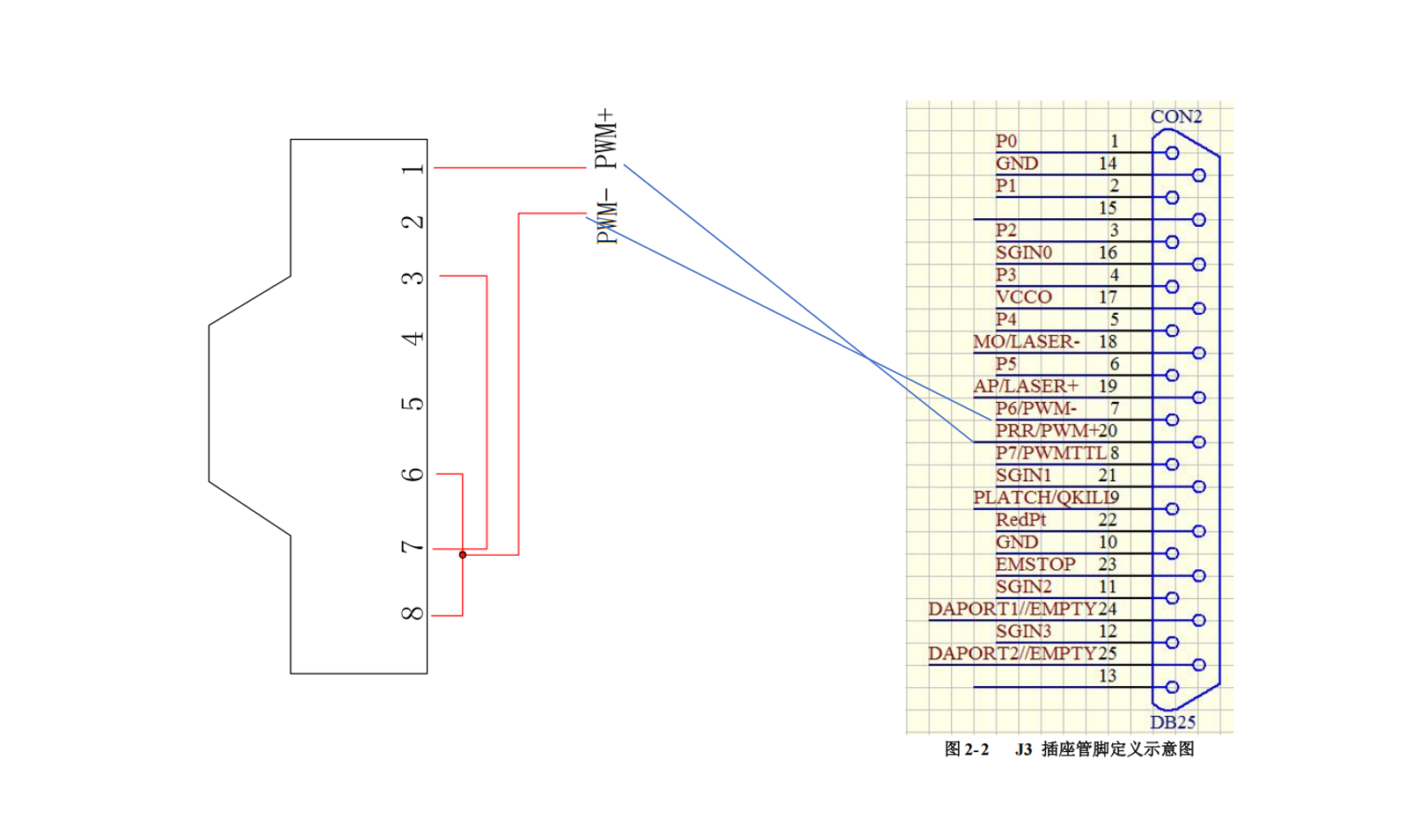
Before wiring, download the original manuals and cross-check the pin definitions:
All J3 (DB25) pins relevant to this machine in CO2/YAG digital mode (per the BJJCZ manual):
| J3 pin | Definition | Treatment on this machine |
|---|---|---|
| Pin20 / Pin7 | PWM+ / PWM− (differential) | PWM+ → RJ45 Pin1; PWM− → RJ45 Pin6+Pin8 (shorted, standard) |
| Pin8 | PWMTTL (alternative TTL) | Unused (leave open unless single-ended modulation is needed) |
| Pin19 / Pin18 | LASER+ / LASER− | Not connected (with the 3/7 shorted fault-gating scheme, LASER± stay open; for active enable use Pin17 via 1 kΩ to RJ45 Pin7 instead — do not wire LASER+ to Pin7, to avoid open-collector/push-pull outputs fighting each other) |
| Pin24 / Pin25 | DAPORT1 (0-10 V analog power) / DAPORT2 (0-5 V frequency / first-pulse suppression) | Unused (in digital CO2 mode power is set by PWM duty cycle) |
| Pin17 | VCCO (5 V output) | Backup active-enable option: via a 1 kΩ resistor to RJ45 Pin7 (Control Enable) to provide a high level; in this case Pin3/7 must NOT be shorted — choose either this or the fault-gating scheme, not both |
| Pin22 | REDPT (red pointer) | Control |
| Pin16 | SGIN0 (general input) | Optionally monitor the ready status via an PC817 optocoupler to RJ45 Pin3 (SGIN0 has an internal pull-up — never connect in parallel directly; leaving it out does not affect marking) |
| Pin9 / Pin23 | QKILL / EMSTOP | Unused (CO2 does not use a Q-switch) |
| Pin1~6 | P0~P5 (no output in digital mode) | Unused |
| Pin10 / Pin14 | GND | Unused (left floating when PWM− returns via RJ45 6+8; only wire Pin6+8 if you use the GND-return scheme) |
| Pin13 / Pin15 / Pin11, Pin12, Pin21 | Empty / SGIN1~SGIN3 | Leave floating (not used on this machine) |
9. J4 IO Pinout: Red Pointer and Foot Pedal Wiring
9.1 Red pointer (J4 OUT4 and GND)
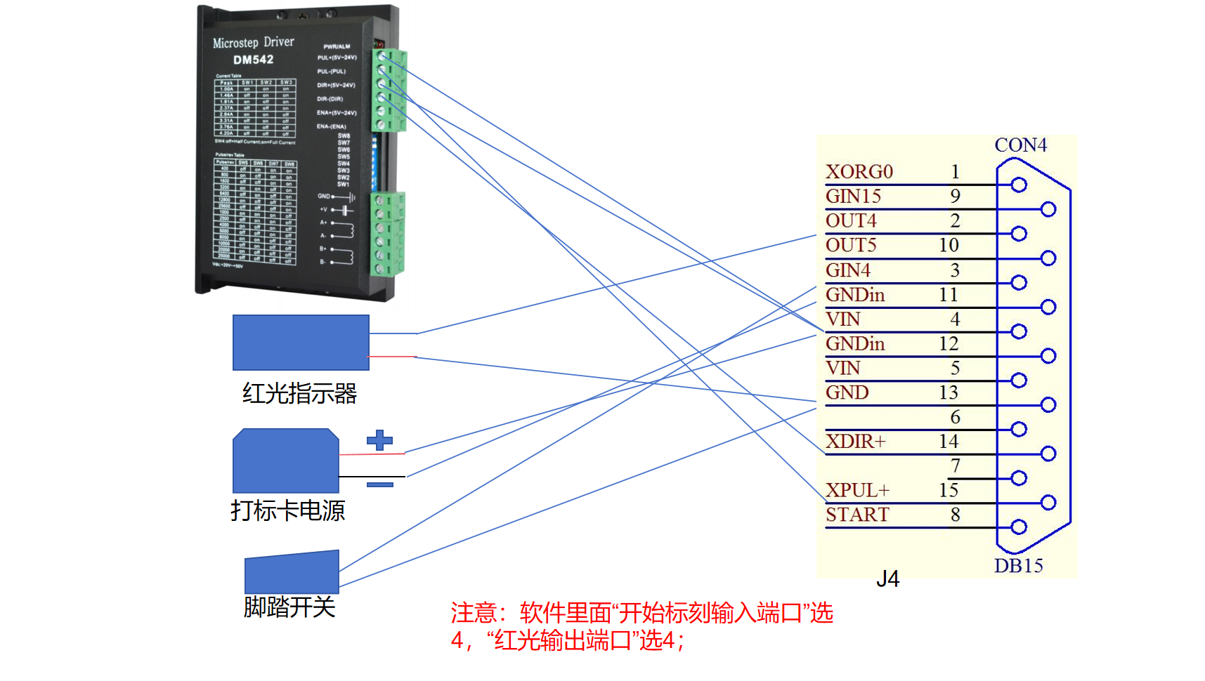
- Of the two wires of the red pointer, connect one to marking card J4 Pin2 (OUT4), and the other to marking card J4 Pin13 (GND), then remember to set the “red pointer output port” in the marking software to port “4“.
9.2 Foot pedal switch (J4 Pin3 GIN4)
- Connect the two ends of a normally open foot pedal switch to J4 Pin3 (GIN4) and GND (any of Pin11~13).
- GIN4 has built-in filtering (it rejects contact bounce below 120 μs), which suits mechanical contacts such as foot pedals and relays; keep the trigger above 200 ms (low-speed mode).
- In the marking software, set the “start marking port” input port to “4“, and foot-pedal marking works.
10. PC Connection and EZCAD Software Configuration
- Connect the industrial PC’s USB 2.0 port to the marking card’s USB port, and install the BJJCZ board driver and the EZCAD software (the version bundled with the card).
- SW2 DIP switch (critical): with power off, set both SW2 DIP positions to the side printed “ON” = CO2/YAG digital mode; the other side (printed positions 1, 2) = fiber mode. If the silkscreen on the card disagrees with the manual, judge by whether EZCAD connects after power-up and whether the laser type CO2 is selectable. Set the DIP switch only with power off — toggling it while powered has no effect.
- Software parameters: select device FBLI-B (LV7) and laser type CO2; try marking frequencies in the 5–20 kHz range (hardware limit 25 kHz; at higher frequencies the pulse width is compressed and peak power drops). The power percentage is the PWM duty cycle; use 30–50% low power for the first test shots.
- Galvo correction: first run the standard grid with the software’s “correct” function, adjusting the gain on the galvo driver board and the correction factor on the marking card to remove barrel/pincushion distortion.
11. Optical Path Installation and Red Pointer Alignment
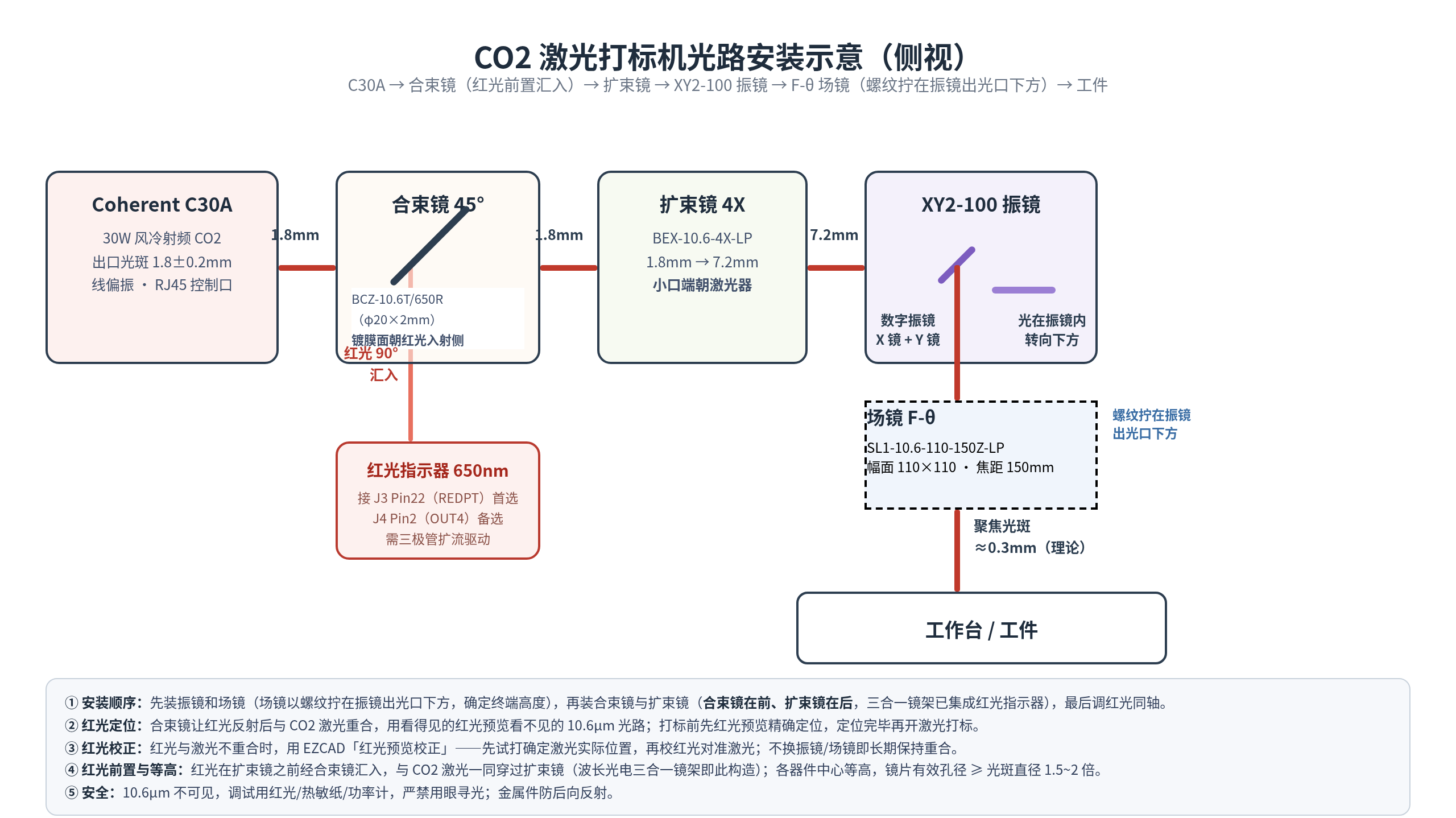
- Installation order: mount the galvo scanner first, thread the F-Theta lens onto the galvo output port below (this fixes the final height), then install the beam combiner and the beam expander (combiner first, expander behind — the Sino Galvo three-in-one mount integrates the red pointer, the beam combiner and the beam expander), and finally perform the red-pointer coaxial alignment.
- Beam expander direction: the small-aperture end of the BEX-10.6-4X-LP must face the laser source; input spot 1.8 mm, output 7.2 mm; the input-side interface is M22×0.75 — match this spec when fitting the laser output bracket or an adapter ring.
- Coaxial equal height: the C30A output port, the beam combiner, the beam expander, and the galvo input port must share the same center height; the effective aperture of each optic should be at least 1.5–2 times the spot diameter (C-series manual FAQ 11).
- Beam combiner at 45°: install it between the laser output port and the beam expander (the red light joins the main path before expansion). The BCZ-10.6T/650R-D20-T2-LP (φ20×2 mm ZnSe bare substrate) transmits the 10.6 μm main laser and reflects 650 nm red light at 45°; the red beam merges with the laser here and passes through the beam expander, the galvo and the F-Theta lens together, staying coaxial the whole way — where the red preview lands is where the laser marks. The Sino Galvo three-in-one mount is built exactly this way, integrating the red pointer, the beam combiner and the beam expander; just follow the markings on the mount on site. Install with the coated side facing the red-light incident side; reversing it produces a ghost image. A 2 mm flat plate tilted at 45° shifts the spot by about 0.5 mm — this is normal and is corrected together during red-pointer alignment.
- F-Theta focusing: the SL1-10.6-110-150Z-LP covers a 110×110 mm work area with a 150 mm focal length (focal length ≠ working distance; the actual working distance follows the Sino Galvo datasheet). The theoretical focused spot is on the order of 0.3 mm; verify with a test shot on thermal paper. If the table height deviates by more than 30% of the depth of focus, the spot visibly grows; find the minimum spot position on thermal paper — that is the focus.
- Red pointer positioning and correction: the beam combiner exists so that the red light, reflected at 45°, overlaps the CO2 laser — using the visible red beam to preview the invisible 10.6 μm laser. Before every marking run, turn on the red preview to position precisely, then fire the laser. If the red preview does not coincide with the actual laser marking position, use the EZCAD “red preview correction”: first make a test shot to determine where the laser actually marks, then turn on the red preview for comparison, and let the correction function shift the red light toward the actual marking position; once corrected, the red preview stays coincident as long as the galvo and the F-Theta lens are not changed. For daily positioning, fine-adjust the beam combiner angle and the red beam direction for quick alignment. Note that the F-Theta lens has chromatic aberration at 650 nm: the red preview is most accurate at the center of the work area and slightly off at the edges, so it suits coarse positioning; for fine positioning rely on a test shot.
Photos of the core optics (original Sino Galvo parts)
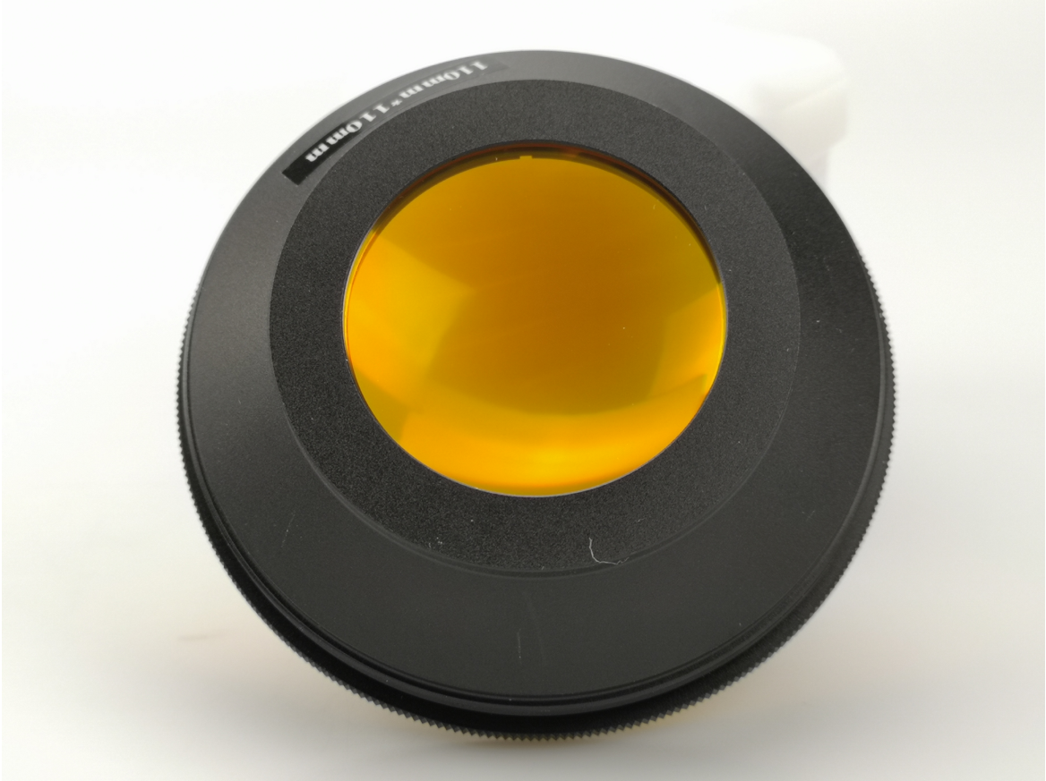
Work area 110×110 mm · focal length 150 mm
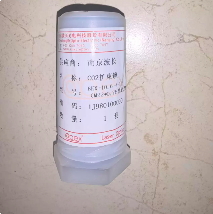
4× expansion · M22×0.75 interface
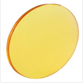
φ20×2 mm · transmits 10.6 μm / reflects 650 nm
12. Power-On Verification Checklist
- □ All wiring complete, PE grounding continuous, multimeter re-check of 48 V / 5 V polarity and voltage.
- □ Power on in order: PC → marking card → galvo → laser source (last).
- □ After power-on the laser pre-ionizes for about 42 seconds; do not fire during this period. After 42 s, LASER OK (RJ45 Pin3) going high only means the ready gate has toggled — power and thermal stability should still be confirmed by a test shot.
- □ EZCAD connects to the board normally and the red preview position is correct.
- □ Place thermal paper or masking tape and make a low-power (30%) low-frequency test shot of a single character; confirm the firing position and work area.
- □ Measure the output power with a power meter against the 30 W rating (depending on the duty-cycle setting); for sensor head selection and range matching see the Ophir power meter selector.
- □ Mark continuously for 30 minutes; check the laser fan and power supply temperature (leave 10 cm of clearance around air-cooled units).
Safety notes specific to CO2 machines (Class 4 — implement every item)
- A 10.6 μm laser is Class 4 (GB 7247.1 / IEC 60825-1); never search for the beam with your eyes. Always use the red pointer, thermal paper or a power meter during alignment.
- Fume from non-metal marking contains particulates and acid gases (PVC releases HCl, polyurethane releases HCN); connect a fume extractor and never vent into the room.
- Wear CO2-specific goggles rated for 10.6 μm (OD ≥ 5); ordinary goggles offer almost no protection at the CO2 wavelength.
- Where possible, add an interlocked protective enclosure and a beam shutter: opening the door cuts the beam, and disengage enable during maintenance.
- Thermal management inside the cabinet: the laser and supplies together dissipate about 700 W; leave at least 10 cm at the exhaust, keep the cabinet below 35°C — excessive ambient temperature triggers temperature protection (the Temperature OK signal goes low).
- Add a 30 mA RCD on the 220 V input; keep a CO2 fire extinguisher on site (never use water-based extinguishers on live equipment).
- Marking metal workpieces carries a back-reflection risk; avoid aiming the beam perpendicular at highly reflective materials to protect the laser output window.
- The laser contains RF high voltage — never open its housing under any circumstances; send it back to the manufacturer for repair.
- During commissioning power only the marking card and the galvo and keep the laser branch de-energized; perform all test firing only after protection is in place.
- ZnSe optics contain selenium; do not touch fragments with bare hands and wear nitrile gloves when cleaning or replacing.
- Before changing the F-Theta lens or the beam combiner, confirm the laser branch is de-energized to prevent accidental firing.
- For long-term shutdown, switch off the 220 V main MCB; do not operate the machine during thunderstorms.
13. Troubleshooting
| Symptom | Possible cause | Fix |
|---|---|---|
| No red light at power-on | OUT4 miswired or a cold solder joint; or the red pointer port in the software was not set to 4 | Check the J4 Pin2 wiring and the red pointer power supply; confirm the red pointer port setting in the software |
| Red light works but no laser | 3/7 not shorted / SW2 not set to ON / laser branch not powered | Check the RJ45 3–7 shorting wire; re-set SW2 with power off; confirm the LRS-600-48 branch switch is closed |
| LASER OK stays low | Pre-ionization not finished (within about 42 s); the laser is in VSWR reflection protection, temperature protection, or 48 V voltage abnormality | Wait and retry; measure 48 V±2%; check output window cleanliness and load matching (VSWR), inspect Pin4/5 status output with an oscilloscope if needed; contact the supplier if still abnormal |
| Laser present but very weak | PWM duty cycle too low; ZnSe optic dirty or coating damaged; frost/contamination on the output window | Raise the power percentage; gently wipe the optic with alcohol and a lint-free cloth (ZnSe coatings scratch easily); confirm the beam expander direction; if still weak, check RF power vs. duty-cycle matching |
| Uneven marking depth / blurry edges | Focus not found; beam not coaxial; F-Theta lens dirty | Refind the focus on thermal paper; redo the red-pointer coaxial alignment; clean the lower surface of the F-Theta lens |
| Marking position differs from preview | Red pointer not calibrated; galvo correction factor wrong; edge offset caused by red-light chromatic aberration | Readjust the beam combiner angle; recalibrate the galvo in software; if the center coincides and only the edges are offset, it is chromatic aberration — rely on a test shot |
| Software cannot find the board | USB cable/driver problem; insufficient 5 V supply | Try another USB port and reinstall the driver; measure 5–5.2 V at J4 |
| Galvo does not move | J1 pin order wrong; galvo power supply not switched on | Verify the DB15 pin order and shield grounding; confirm the galvo branch switch |
| Laser stops automatically during marking | Temperature protection; 48 V ripple out of spec; duty cycle too high | Improve cooling; replace the supply with a compliant one; reduce the duty cycle and retry |
14. Parts Procurement and Support
Soar Laser can supply the Coherent C30A, the BJJCZ marking card, Mean Well power supplies, Sino Galvo F-Theta lens / beam expander / beam combiner, and the XY2-100 digital galvo scanner covered in this guide, together with matching technical guidance. For a complete machine solution, selection alternatives (e.g., higher-power C series), or procurement on your behalf, feel free to contact us.
- Hotline: 15927220467 | Email: 859818709@qq.com
- Further reading: Fiber Laser Marking Machine Assembly Guide (previous article) | CO2 Laser Source Encyclopedia | Galvo Scanner Selection Guide | Laser Safety Classes and Protection Encyclopedia
Disclaimer: This guide is based on the Coherent “New C-Series Laser User Guide” and the BJJCZ “FBLI-B-LV7 Card Manual V4.0.9” and is provided for technical reference only. Always defer to the latest manual of the components in hand for actual wiring; laser operation carries a risk of injury and should be performed by trained personnel in compliance with laser safety standards.
Leave a Reply