


What Is an Optical Cable? The Armour and the Skeleton of a Fibre
An optical cable is a cable product made by packaging one or more fibres into a protective envelope. A bare fibre has excellent optical performance but is very fragile — the glass breaks easily and is sensitive to moisture, chemical attack and mechanical stress. The cable gives the fibre mechanical protection, resistance to moisture and corrosion and immunity to interference. From a patch cord to a transoceanic submarine cable the shapes differ widely, but the goal never does: protect the fibre without impairing its optical performance.
Table of contents
- 1. What is an optical cable? Getting the core concept straight
- 2. Structure: what each layer of an optical cable does
- 3. Key parameters: reading the specifications of an optical cable
- 4. Main types: what kinds of optical cable are there
- 5. Applications: where is optical cable used?
- 6. Common misconceptions: pitfalls to avoid
1. Core concept: what is an optical cable?
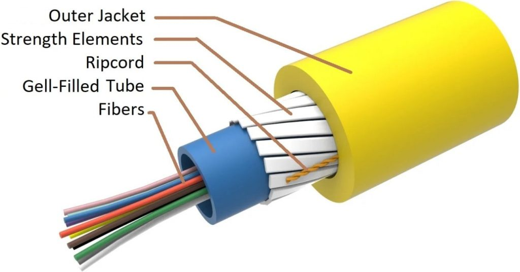
An optical cable is a cable product made by packaging one or more optical fibres into a protective envelope. A bare fibre has excellent optical performance but is very fragile on its own — the glass breaks easily and is sensitive to moisture, chemical corrosion and mechanical stress. The cable gives the fibre mechanical protection, resistance to moisture and corrosion and immunity to interference, so that it can be used reliably in any environment. The structural forms range from indoor patch cords to transoceanic submarine cables, but the objective is always the same: protect the fibre while keeping its optical performance intact.
2. Structure: what each layer of an optical cable does
Typical layer structure of an optical cable (from the inside out)
- Fibre core: the glass fibre that carries the optical signal, 125 μm in diameter (cladding), 250 μm once the coating is applied
- Colour layer: the coloured coating on the fibre surface (a 12-colour code), used to tell the fibres of a multi-fibre cable apart
- Buffer layer: a tight buffer (900 μm) or a loose tube (filled with gel), providing mechanical cushioning and protection against moisture
- Strength members: steel wire, FRP (glass-fibre reinforced plastic) or aramid yarn (Kevlar), providing the tensile strength
- Water barrier: water-blocking yarn, tape or filling compound, preventing longitudinal water ingress
- Inner jacket / armouring: steel tape or aluminium tape armour, giving resistance to crushing and to rodent damage
- Outer jacket: PE (polyethylene), LSZH (low smoke, zero halogen) or AT (anti-termite), the environmental protection layer
Principle of strain isolation: the core of the cable design is to keep the strain in the fibre far below its breaking strain (about 1%) and below the added-loss threshold when the fibre is stretched, bent or heated. The strength members carry the main tensile load and the buffer layer isolates the fibre from external stress.
Fibre coating
is the innermost protection and is applied directly to the outside of the bare fibre (cladding diameter 125 μm), usually in acrylate, silicone or polyimide, about 60-100 μm thick. Its job is to protect the glass surface from the initiation and the growth of microcracks — the strength of glass depends mainly on the quality of its surface, and a tiny scratch spreads rapidly under stress until the fibre breaks. The coating takes no part in guiding the light and has to be stripped before use.
The buffer layer
A tight buffer or a loose buffer sits outside the coating. A tight buffer is a stiff plastic layer (typically 900 μm in outer diameter) wrapped directly around the coated fibre, giving extra mechanical protection; it is common in indoor patch cords. A loose buffer instead places the fibre in a plastic tube filled with a water-blocking gel, and the fibre can move freely inside it; this structure copes better with temperature changes and tension and is common in outdoor cables.
The strength members
give the cable its tensile strength. The usual materials are aramid yarn (such as Kevlar), glass-fibre reinforced plastic (FRP) and steel wire. They take the pull applied while the cable is being laid and keep the fibre itself free of tensile stress.
The outer jacket
is the outermost protection and is usually made of polyethylene (PE) or PVC, giving protection against moisture, corrosion, ultraviolet light and abrasion. Different environments call for different jacket materials — low smoke zero halogen (LSZH) for indoor use, and an armouring layer for direct burial or for areas with a serious rodent problem. One important principle of cable design is strain isolation: the mechanical effects of external pull, pressure and bending should be carried by the strength members and the jacket instead of being passed on to the fibre. The fibre inside the cable should stay at “zero strain” or at low strain so that the optical performance stays stable over the long term.
3. Key parameters: reading the specifications of an optical cable
Bend loss: macro-bending and micro-bending
Bending is a loss mechanism that has to be considered carefully in the design and use of an optical cable, and it falls into two categories:
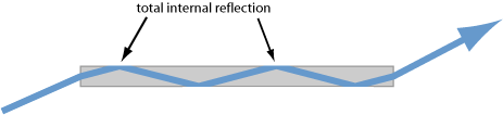
① Macro-bending loss: caused by the large-radius bending of the cable as a whole. Once the bend radius becomes small enough, part of the energy of the guided mode leaks out in the form of radiation modes. For a standard single-mode fibre the macro-bending loss is usually negligible above a bend radius of 30 mm, but above 1550 nm the sensitivity to bending increases markedly.
② Micro-bending loss: caused by small deformations of the fibre surface or by local pressure, typically arising when the fibre is squeezed against the buffer or the strength members during manufacture, or from material shrinkage as the temperature changes. Micro-bending loss is wavelength-dependent as well — the longer the wavelength, the larger the micro-bending loss.
💡 Why is the bend loss wavelength-dependent?
The longer the wavelength, the larger the mode field diameter and the more diffuse the optical field, so the evanescent field reaches further into the cladding. When the fibre is bent, the part of the evanescent field away from the centre of the bend would have to keep up at a phase velocity greater than that of light, which is impossible, so that energy leaks away as radiation. The longer the wavelength, the more leaks and the larger the loss.
Attenuation coefficient of an optical cable
The attenuation coefficient of a cable (in dB/km) is the most important transmission figure of an optical cable. It is made up of the loss of the fibre itself (absorption and scattering) plus the additional losses introduced during cable manufacture (micro-bending, strain losses and so on).
A typical G.652 cable has an attenuation coefficient of about 0.20-0.25 dB/km at 1550 nm and about 0.33-0.40 dB/km at 1310 nm. Indoor cables have a slightly higher attenuation because of their compact structure and the many bends they go through.
Reading the key parameters is the starting point for assessing the performance of an optical cable. The table below sets out the main specifications and what they mean:
| Parameter | Meaning | Engineering significance |
|---|---|---|
| Number and type of fibres | The number of fibres in the cable (such as 12, 24 or 144 cores) and their type (single-mode, multimode and so on) | It sets the transmission capacity and where the cable can be used: more cores mean more capacity, and the fibre type decides both the transmission performance and the cost. |
| Jacket diameter | The overall outer diameter of the cable | It sets how much space the cable takes up and how full a duct can be; a thicker cable needs more space to lay and costs more to install. |
| Allowed tensile load | The maximum pull allowed during installation and in service, with different short-term and long-term values | It sets the maximum pulling force during laying and the tension the cable can take in service, which matters for both the design and the safety of the work. |
| Allowed crushing load | The lateral pressure the cable may withstand | It shows how well the cable resists side pressure and therefore how much mechanical protection it gives when buried or pulled through a duct. |
| Minimum bend radius | The static and dynamic bend radii that keep the loss and the mechanical damage within limits | It sets how tightly the cable may be bent during installation and how much space it needs; a smaller radius makes the routing easier but raises the loss. |
| Operating temperature range | The range of ambient temperatures over which the cable works correctly | It defines where the cable can be used, and any degradation at extreme temperatures hits the reliability of the system, which matters most outdoors and in industry. |
| Temperature coefficient of attenuation | The additional loss caused by a change in temperature | It measures how strongly the loss follows the temperature; the smaller the coefficient, the more stable the link stays at extreme temperatures. |
| Fire rating | The fire safety class of an indoor cable | It decides how the cable behaves in a fire, which is a safety requirement that has to be met indoors and in sealed spaces such as data centres. |
| Service life | The expected number of years of reliable operation | It sets the whole-life cost of the cable; a long-lived cable costs more at the start but less over its life in maintenance and replacement. |
4. Main types: what kinds of optical cable are there?
Common optical cable constructions
- Loose-tube cable: several loose tubes are helically wound around a central strength member, giving a high core count (12-288 cores); used in backbone and access networks
- Central-tube cable: all the fibres sit in one central loose tube; compact, light and suitable for aerial and duct installation
- Ribbon cable: the fibres are arranged in ribbons (12 fibres per ribbon), which allows very high fibre counts (over a thousand cores); used in data centres and core networks
- ADSS cable: all-dielectric self-supporting, with no metal, so it can be attached directly to power pylons; used for power system communications
- OPGW cable: optical ground wire, combining the function of a ground wire with that of a communication line; used on high-voltage transmission lines
- Submarine cable: multiple armour layers and a water barrier, taking the high water pressure and the tension of laying; transoceanic links run for thousands of kilometres
- Armoured cable: steel tape or steel wire armour, giving resistance to rodents and crushing; used for direct burial and in special environments
Optical cable can be classified in many ways, and each dimension helps you understand its characteristics from a different angle. The most common ones are introduced below:
By the environment it is used in
Indoor optical cable
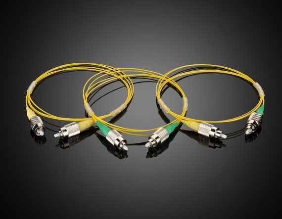
Light, flexible and flame-retardant: patch cords, pigtails and wiring cable
Outdoor optical cable
A high protection level against water, ultraviolet light and a wide temperature range
Direct-burial cable
Carries an armouring layer so it can be buried directly in the ground
Duct cable
Laid in underground ducts
Aerial cable
Strung between poles or towers
Submarine cable
Water and mechanical protection to the highest standard, for links that cross the sea
By structural form
Loose-tube cable
Several loose tubes helically wound around a central strength member; the mainstream outdoor cable because it holds a large number of fibres
Central-tube cable
All the fibres in one central tube; compact in structure
Ribbon cable
The fibres are stacked in ribbons; high density and easy to splice in large numbers
Indoor wiring cable
Branch and distribution cable for use inside a building
By special purpose
Armoured cable
A metal or non-metal armouring layer, giving resistance to rodents and impact
Anti-termite cable
A special jacket that keeps termites out
High-power delivery cable
For carrying high-power laser light, with a special end-face treatment and heat-dissipation design
Aerospace cable
Light in weight and able to survive extreme environments
5. Applications: where is optical cable used?
The applications of optical cable span several fields; the main directions are:
- Communication backbone networks: the long-distance cables that cross cities and oceans are the physical foundation of the global internet
- Access networks: the outdoor and indoor cables used for fibre to the home (FTTH) bring high-speed internet to every household and business
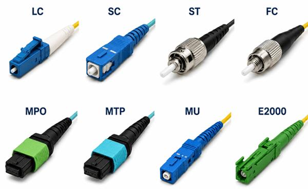
- Data centres: large amounts of cable (patch cords, MTP/MPO ribbon cable) inside a data centre carry the high-speed links between servers and switches
- Industrial laser systems: high-power laser light is carried from the source to the processing head, as in laser cutting, welding and marking equipment
- Medical equipment: laser surgery units and endoscope systems use dedicated medical optical cable
- Sensing and monitoring: distributed fibre sensing systems use special cables to monitor temperature, strain and vibration, for the structural health of pipelines, bridges and tunnels
- Military and aerospace: special cables are used in radar, ships, aircraft and satellites
👉 Want to see more real application cases? Visit the application case page of Soar Laser, or contact our technical team directly for professional advice.
6. Common misconceptions
Misconception 1: an optical cable is just a bundle of fibres tied together
An optical cable is far more than a bundle of fibres. It is a carefully designed mechanical protection system that normally includes, from the inside out, the fibre, the coating, the buffer layer (tight or loose), the strength members (aramid yarn, steel wire or glass-fibre reinforced plastic) and the outer jacket, with an armouring layer and a water barrier on some special cables. Together these structures keep the fibre performing steadily in harsh conditions (pull, pressure, bending, temperature change, water ingress, rodent damage). “Tied together” badly understates how much engineering goes into an optical cable.
Misconception 2: the thicker the cable, the more fibres it holds
The thickness of a cable and the number of fibres it holds do not simply go together. Different structures hold very different fibre counts in the same outer diameter: a ribbon cable can hold more than a thousand cores in a limited space, while the core count of a loose-tube cable is limited by the number and the size of its tubes. The outer diameter depends much more on the mechanical strength required (the thickness of the strength members), on the protection level (the thickness of the armouring) and on the environment (the jacket material) than on the fibre count alone.
Misconception 3: a direct-burial cable is simply buried in the soil
A direct-burial cable really is installed directly in the ground, but it is not simply a trench with the cable dropped in. Direct burial follows strict practice: a trench is dug and bedded with fine sand, the cable is laid and backfilled with fine soil, and a warning tape, bricks or a concrete protection slab may be placed on top. The cable itself also needs enough mechanical strength (such as steel wire armouring) and corrosion resistance to withstand the pressure of the soil, groundwater and possible mechanical damage.
Misconception 4: indoor and outdoor cables differ only in their jacket
Indoor and outdoor cables differ in far more than the jacket. An outdoor cable has to cope with extreme temperature swings, ultraviolet radiation, immersion in rain and mechanical pull, and it normally carries strength members, a water barrier and a thick outer jacket; an indoor cable concentrates on flame retardancy (an LSZH jacket), flexibility and environmental requirements, and its structure is simpler. More importantly, the fibre type may differ as well — an outdoor cable may use long-distance single-mode fibre such as G.652, while indoor wiring may use multimode fibre or tight-buffered single-mode fibre. Mixing them up can leave the performance short of the specification or create a safety hazard.
7. Recommended reading
- What is an optical fibre? How light travels thousands of kilometres in a glass thread
- What is single-mode fibre? Why communication networks use it
- What is an optical waveguide? How light is guided without a fibre
- What is a fibre laser? Why it dominates the industrial laser market
- Laser coherence and coherence length
Leave a Reply