


What Is a Fused Fibre Coupler? How Two Fibres Split Light
A fused fibre coupler is an all-fibre coupling device made by a heated fused-tapering process, and it can distribute or combine the optical power between two or more fibres. The basic principle is this: two (or more) fibres have their coating stripped and are brought into close contact, and at a high temperature the glass is fused while the assembly is drawn out into a tapered coupling region. In that region the cores become very thin and close to each other, their evanescent fields overlap and the optical power can transfer back and forth periodically between the two fibres. By controlling the length of the taper the power distribution (the splitting ratio) can be set precisely. Fused couplers have a low insertion loss, a compact structure, an all-fibre build and a high reliability, which makes them one of the most fundamental passive devices in a fibre system.
Table of contents
- 1. What is a fused fibre coupler? Getting the core concept straight
- 2. Working principle: how a fused fibre coupler is achieved
- 3. Key parameters: reading the specifications of a fused fibre coupler
- 4. Main types: what kinds of fused fibre coupler are there
- 5. Applications: where is a fused fibre coupler used?
- 6. Common misconceptions: pitfalls to avoid
1. Core concept: what is a fused fibre coupler?
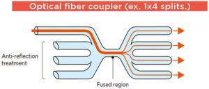
A fused fibre coupler is an all-fibre coupling device made by a heated fused-tapering process, and it can distribute or combine the optical power between two or more fibres. The basic principle is this: two (or more) fibres have their coating stripped and are brought into close contact, and at a high temperature the glass is fused while the assembly is drawn out into a tapered coupling region. In that region the cores become very thin and close to each other, their evanescent fields overlap and the optical power can transfer back and forth periodically between the two fibres. By controlling the length of the taper the power distribution (the splitting ratio) can be set precisely. Fused couplers have a low insertion loss, a compact structure, an all-fibre build and a high reliability, which makes them one of the most fundamental passive devices in a fibre system.
2. Working principle: how is a fused fibre coupler achieved?
Evanescent field coupling
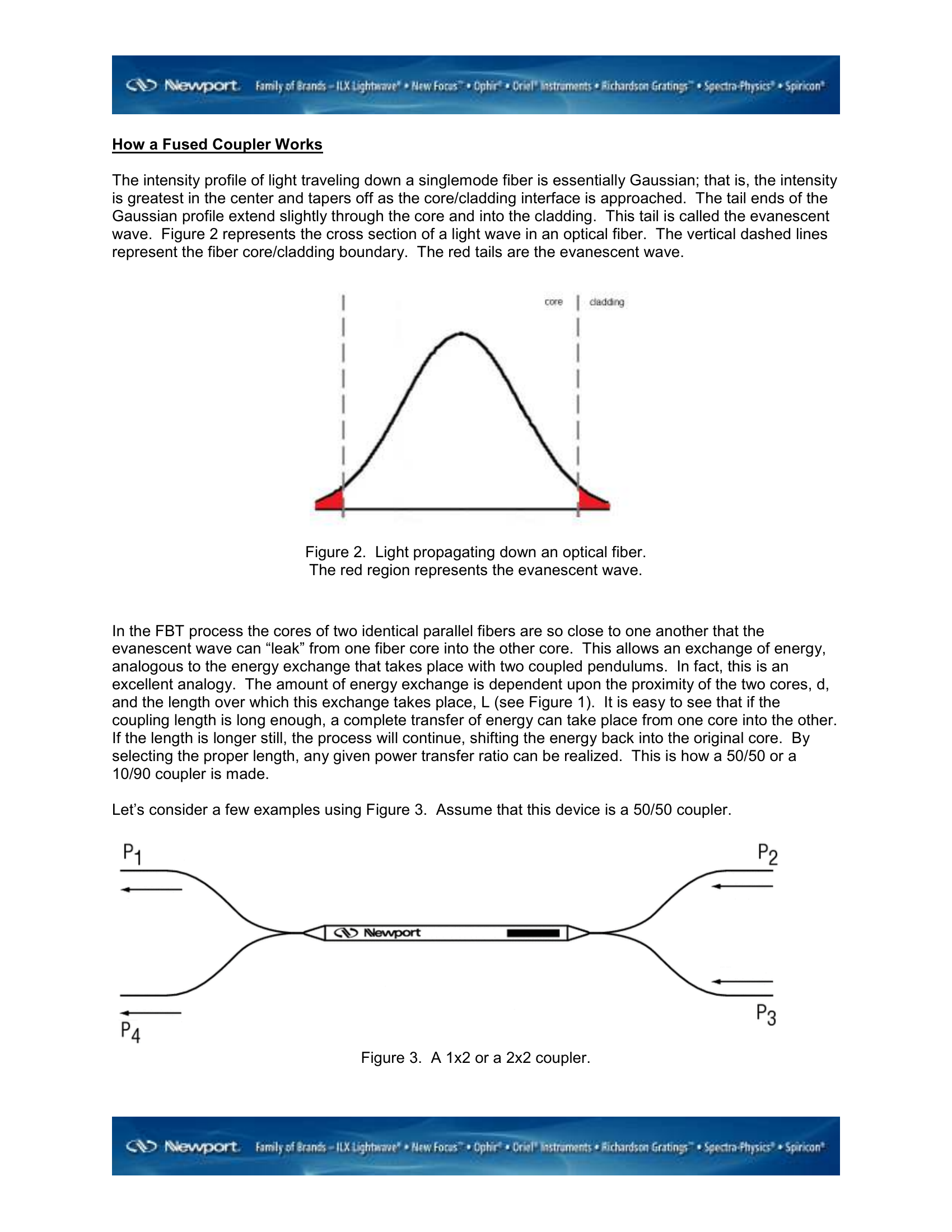
The core mechanism of a fused coupler is evanescent field coupling. When two fibres are brought within a certain distance of each other (usually within a few micrometres), part of the field carried by each of them extends into the cladding as an evanescent wave, and these evanescent fields can overlap, which transfers energy from one fibre to the other.
The coupling strength depends mainly on:
- The gap between the fibres: the smaller the gap, the stronger the coupling
- The wavelength: the longer the wavelength, the further the evanescent field reaches and the stronger the coupling
- The length of the coupling region: the longer the coupling length, the more complete the transfer of energy
💡 Why does tapering strengthen the coupling?
Tapering makes the fibre thinner, so the core diameter shrinks, the V parameter falls and the mode field spreads out more — more of the optical energy “leaks” into the cladding and the evanescent field reaches further. At the same time the two fibres move closer together in the tapered region and the overlap area grows; the two effects together raise the coupling efficiency considerably. Two standard fibres that are merely pressed together, without any taper, couple very poorly.
The manufacturing process
runs roughly as follows: 1. strip the coating from the middle section of the two fibres to expose the cladding 2. twist the two fibres together so that they touch closely 3. heat the contact region with a flame or a heating source until the glass fuses 4. pull the fibres slowly while they are still molten, forming a biconical structure (the coupling region) 5. control the taper length by monitoring the optical power at the output until the target splitting ratio is reached
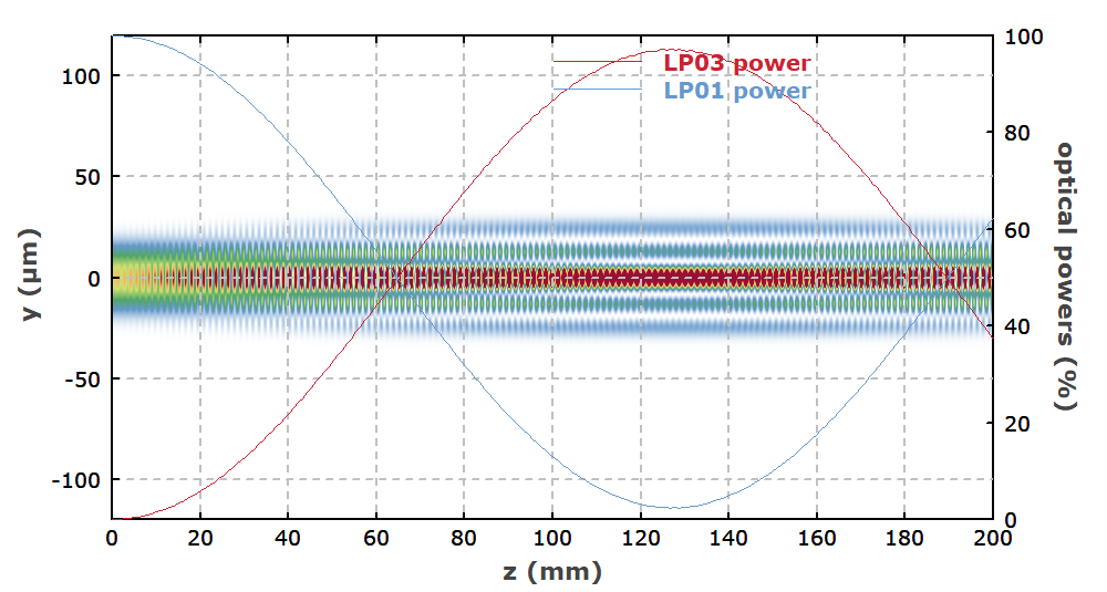
In the coupling region the original core becomes very thin because the fibre has been drawn down, so the optical field spreads strongly into the cladding, which amounts to a supermode forming in the “common cladding” of the two fibres. As the light travels through the coupling region the energy oscillates periodically between the two fibres. The longer the coupling length, the more complete the transfer.
The splitting ratio of a fused coupler is sensitive to the wavelength, because both the coupling strength and the coupling period depend on it. According to this wavelength behaviour, fused couplers are classified into:
Single-window coupler: the splitting ratio is accurate near one particular wavelength
Broadband coupler: the splitting ratio stays relatively flat over a wide wavelength range
Dichroic coupler: uses the wavelength selectivity to combine or to separate two different wavelengths (such as pump light and signal light)
3. Key parameters: reading the specifications of a fused fibre coupler
Directivity
Directivity is the parameter that measures the isolation of a coupler, defined as the ratio of the power at the input port to the power that leaks back to the other input port (in dB). The higher the directivity, the better the port isolation.
Directivity = 10·log₁₀(P_input / P_leakage_back) [dB]
A good fused coupler has a directivity above 55 dB. Poor directivity causes signal crosstalk and degrades the performance of the system.
WDM coupler working principle
The wavelength division multiplexing (WDM) coupler makes use of the wavelength dependence of the coupler — the coupling efficiency differs from one wavelength to the next at the same coupling length. By controlling the taper length precisely, one wavelength (such as 980 nm) can be coupled almost entirely into the other fibre while another (such as 1550 nm) hardly couples at all, which combines or separates the two wavelengths.
The common WDM pairs are: 980/1550 nm (EDFA pump combining), 1310/1550 nm (single-mode communication multiplexing), 1480/1550 nm and so on.
Core formulas
Coupling coefficient and splitting ratio: two identical fibres couple through the evanescent field in the fused tapered region, and the power oscillates along the coupling length:
P₁(z) = P₀ · cos²(κz)
P₂(z) = P₀ · sin²(κz)
where κ is the coupling coefficient (which depends on the fibre separation and on the mode overlap) and z is the length of the coupling region. When κz = π/2 the power has transferred completely to the other fibre (the 3 dB coupler).
Coupling coefficient and wavelength: the coupling coefficient κ varies with the wavelength — the mode field is larger at long wavelengths, the evanescent field reaches further and the coupling is stronger. The splitting ratio of a fused coupler is therefore wavelength dependent and its bandwidth is limited. A broadband coupler needs a special taper design.
Reading the key parameters is the starting point for assessing the performance of a fused coupler. The table below sets out the main specifications and what they mean:
| Parameter | Meaning | Engineering significance |
|---|---|---|
| Splitting ratio (coupling ratio) | The share of the total power that goes to each output port, such as 50:50, 90:10 or 99:1 | It sets how the power is shared between the output ports, which is the central figure when a coupler is chosen and a system is designed, and it feeds directly into the link budget and the signal distribution strategy. |
| Insertion loss | The total power loss as the light passes through the coupler; a good tapered coupler can be below 0.1 dB | The total power loss through the coupler; the lower it is the better |
| Return loss | The ratio of the power reflected back to the input port to the incident power, usually above 50 dB | The ratio of the reflected light to the incident light; the higher it is the better, usually above 50 dB |
| Operating bandwidth | The wavelength range over which the splitting ratio stays within specification | The range over which the performance is met, such as ±40 nm or the C and L bands |
| Polarisation dependent loss (PDL) | The difference in the insertion loss between different input polarisation states | The difference in the insertion loss between the polarisation states; the lower it is the better |
| Directivity | The isolation of the directional coupler, a measure of how much light travels back from the output to the input | It isolates the reverse crosstalk between the ports |
| Power handling | The maximum optical power the device can take | The maximum optical power at which the coupler can safely operate |
| Operating temperature range | The temperature range over which the device performs reliably | It defines where the device can be used, and any degradation at extreme temperatures hits the reliability of the system, which matters most outdoors and in industry. |
4. Main types: what kinds of fused fibre coupler are there?
The main types of fused fibre coupler and their applications
| Type | Structure | Typical application |
|---|---|---|
| 1×2 / 2×2 splitter | The most basic structure | Power distribution, signal monitoring |
| Broadband coupler | A special taper design | 1260-1650 nm wide-band operation |
| WDM multiplexer | Two-window taper design | 980/1550 nm and 1310/1550 nm pump combining |
| Pump combiner | Several pump fibres plus one signal fibre | Pump combining for a fibre laser (N×1) |
| Tap coupler | A large splitting ratio (such as 99:1) | Inline power monitoring |
| N×N star coupler | Several fibres fused and tapered together | Optical distribution networks, local networks |
Fused fibre couplers can be classified in many ways, and each dimension helps you understand their characteristics from a different angle. The most common ones are introduced below:
By port count
2×2 coupler
The most basic form, with two inputs and two outputs
1×2 splitter
A 2×2 coupler with only one input used, splitting the light into two paths
N×N star coupler
Several input and output ports, such as 4×4 and 8×8
Tap coupler
A splitter with a widely unequal ratio (such as 99:1), taking off a little light for monitoring
By function
Power splitter / combiner
Splits one path into several, or the other way round
Wavelength division multiplexer (WDM)
Uses the wavelength dependence to combine or to separate different wavelengths, such as a 980/1550 nm WDM
Pump combiner
Combines several pump sources into a double-clad fibre in high-power applications
Polarisation-maintaining coupler
Built from polarisation-maintaining fibre so that the polarisation state is held
By operating bandwidth
Single-wavelength coupler
Optimised for one particular wavelength
Broadband coupler
A stable splitting ratio over a wide wavelength range
5. Applications: where is a fused fibre coupler used?

The applications of fused couplers span several fields; the main directions are:
- Fibre lasers: as the output coupler and the pump combiner, it is a key passive device in a fibre laser
- Fibre amplifiers: WDM couplers are used in amplifiers such as the EDFA to combine the pump light with the signal light
- Optical communication systems: for CATV signal distribution, optical splitters and wavelength multiplexing
- Fibre sensing: in fibre interferometers (such as Mach-Zehnder and Michelson) a coupler splits and recombines the light
- Fibre optic gyroscopes: the polarisation-maintaining coupler is one of the core devices of a fibre optic gyroscope
- Optical power monitoring: a tap coupler (such as 95:5) takes off a little light for monitoring without disturbing the main path
- Passive optical networks (PON): the optical splitters of the optical distribution network
👉 Want to see more real application cases? Visit the application case page of Soar Laser, or contact our technical team directly for professional advice.
6. Common misconceptions
Misconception 1: the splitting ratio of a fused coupler is fixed exactly
The splitting ratio of a fused coupler depends to some extent on the wavelength and on the temperature. For a broadband source the ratio may differ slightly from one wavelength to the next, and a change in temperature causes a drift because the refractive index of the material and the structure change slightly. A precise taper process reduces these dependences but cannot remove them. What is more, the further the working wavelength is from the design wavelength, the larger the deviation of the splitting ratio tends to be.
Misconception 2: a coupler can only split light, it cannot combine it
A fused coupler is a reciprocal passive device — the light entering ports A and B and leaving port C combined follows the same power distribution as the light entering port C and leaving ports A and B split (reciprocity). A coupler can therefore serve as a splitter (1×2 or 2×2) and as a combiner (such as a pump combiner or a WDM coupler). One point to watch: combining multimode light with single-mode light can run into a mode mismatch.
Misconception 3: the lower the insertion loss, the better the coupler
The insertion loss is only one of the figures that describe a coupler. The splitting ratio accuracy, the polarisation dependent loss (PDL), the directivity (isolation), the return loss, the temperature stability and the wavelength bandwidth all have to be weighed as well. A coupler with a very low insertion loss but a high PDL, for instance, is simply unusable in a polarisation-sensitive system. The weight of each figure also depends on the application — a communication system cares more about the PDL and about unit-to-unit consistency, a high-power system about the damage threshold.
Misconception 4: the two outputs of a 2×2 coupler are always 50% each
The splitting ratio of a fused coupler is set by the degree of tapering. During the pull the power moves back and forth periodically between the two outputs (power coupling), and 50:50 is only one of countless possible states. By controlling the taper length precisely, couplers with ratios such as 80:20, 90:10 and 99:1 can be made. A WDM coupler works in a different way: it exploits the fact that different wavelengths have different coupling periods during the pull, so that each wavelength leaves from a different port.
7. Recommended reading
- What is an optical fibre? How light travels thousands of kilometres in a glass thread
- What is fibre coupling? How to get laser light efficiently into a fibre
- Fibre coupling technology and coupling efficiency
- What is a fibre Bragg grating? The reflective grating inside a fibre
- What is active fibre? The fibre that amplifies light
Leave a Reply