


A complete guide to flat-field / scan lenses, from physical principles to technical selection
Updated: September 06, 2026
Compiled from: RP Photonics Encyclopedia authoritative entries · Soar Laser 5 selection guides · Thorlabs/CASTech/SPIE technical data
I. Terminology: Flat-Field Lenses, Scan Lenses, and F-Theta Lenses
A flat-field lens is a lens system whose core function is to correct field curvature aberration and achieve flat focusing across the entire field. Its mission is to “flatten” the curved Petzval surface so that beams at different field angles all focus on the same physical plane.
A scan lens (field lens / scan lens) is the laser-processing industry’s short name for a flat-field scanning lens, specifically the flat-field focusing optical assembly used in galvanometer scanning systems. In laser marking, cutting, and welding, the scan lens is the core component at the end of the optical path, converting the angle-scanned beam reflected by the galvos into a position-scanned spot on a flat plane.
An F-Theta lens is the most mainstream subclass of flat-field scanning lenses. On top of flat focusing, it deliberately introduces barrel distortion (negative distortion) to cancel the nonlinear relation y = f·tanθ of ordinary lenses, achieving an approximately linear relation y ≈ f·θ between image height and scan angle, so that a spot moves at constant speed across the work surface when the galvo rotates at constant speed.
The three in one sentence: a flat-field lens is the “big umbrella” (all field-curvature-correcting lenses), a scan lens is the flat-field scanning lens used in laser scanning, and F-Theta is the most common subclass of scan lens, with linear scanning correction. An F-Theta is always a flat-field lens, but a flat-field lens is not always an F-Theta.
In laser processing, the everyday term “scan lens” is nearly synonymous with “F-Theta flat-field scanning lens.” This article focuses on F-Theta scan lenses for laser scanning, while also covering advanced types such as telecentric and achromatic scan lenses.
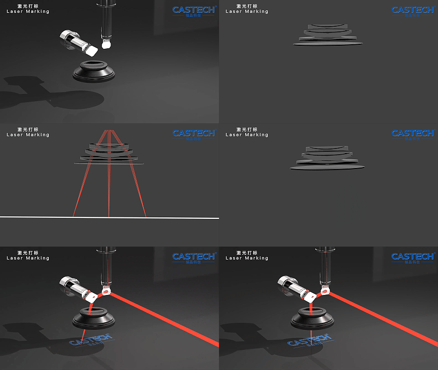
Figure 1 Complete optical path of a galvanometer scanning system
Source: CASTECH
II. Physical Principles: From Petzval Curvature to F-Theta Linear Scanning
2.1 Petzval Field Curvature Theory – Why Is the Focal Surface of an Ordinary Lens Curved?
Field curvature is an inherent aberration of spherical lenses. For a single positive lens, on-axis rays (centre field) converge at one focus, while off-axis rays (edge field), due to oblique incidence, converge at a focus closer to the lens than the on-axis focus. Connecting the foci of all fields forms not a plane but a surface concave toward the lens – this is the Petzval surface.
The magnitude of field curvature can be quantified by Petzval curvature. For an optical system composed of k refracting surfaces:

where nᵢ and n’ᵢ are the refractive indices before and after the i-th refracting surface, and rᵢ is the radius of curvature of that surface. Two key conclusions follow from the formula:
- A positive lens produces positive field curvature (focal surface curves toward the object, focus closer to the lens)
- A negative lens produces negative field curvature (focal surface curves toward the image, focus farther from the lens)
This is the core idea of flat-field correction: by properly combining positive and negative optical-power elements, the total Petzval curvature approaches zero. But completely eliminating field curvature physically conflicts with beam focusing – all flat-field systems have residual field curvature, only of different magnitudes. [(RP Photonics: Scanning Lenses)](https://www.rp-photonics.com/scanning_lenses.html)
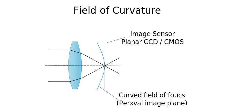
Figure 2 Petzval field curvature principle: ordinary lens curved focal surface vs flat-field lens flat focal field
Source: internet
2.2 Four Technical Routes for Flat-Field Correction
According to SPIE academic literature on F-Theta lens optical design, flat-field correction mainly follows four technical routes:
| Technology route | Optical structure | Correction effect | Complexity / cost | Applicable scenario |
|---|---|---|---|---|
| Positive + negative lens combination + air gap | Different-index glasses paired, with an air gap in between | Moderate, relatively large residual field curvature | Low / low | Small field, low precision |
| Plano-concave lens structure | Plano-concave negative lens near the image side | Moderate | Medium / medium | General marking |
| Thick meniscus lens | Thick meniscus optimises the Petzval sum by thickness | Good | Medium / medium-high | Medium-high precision |
| Multielement complex structure + aspheric | 3-7 lens elements, including aspheric elements | Excellent, field curvature controllable at micron level | High / high | High precision, telecentric, large field |
Table: Comparison of four flat-field correction routes. Core rule: a flat-field system contains at least one negative-power element; a zero Petzval sum inherently conflicts with beam focusing, so real systems always have residual field curvature. [(SPIE: Optical design and performance of F-Theta lenses)](https://www.spiedigitallibrary.org/conference-proceedings-of-spie/9626/96261S/Optical-design-and-performance-of-F-Theta-lenses-for-high/10.1117/12.2190777.pdf)
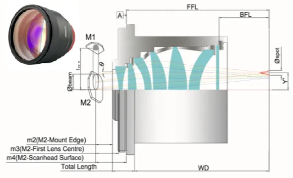
Figure 3 Cross-section of a multielement lens group in an industrial F-Theta scan lens
Source: Astron Japan (Ronar-Smith®)
2.3 F-Theta Distortion Correction – The Deliberately Introduced “Useful Distortion”
An ordinary flat-field scanning lens follows the tangent relation y = f·tanθ for image height, which is nonlinear – when the galvo rotates at constant speed, the spot moves faster at the edge than at the centre, causing pattern distortion and uneven processing.
The innovation of the F-Theta lens: deliberately introducing a precise amount of barrel distortion (negative distortion) “flattens and straightens” the tangent curve, making image height approximately linear with scan angle: y ≈ f·θ.
The tangent image height of an ordinary lens is y_tan = f·tanθ, and the F-Theta target image height is y_θ = f·θ; their difference can be calculated quantitatively (negative for θ>0, i.e. the barrel distortion amount that must be designed in):
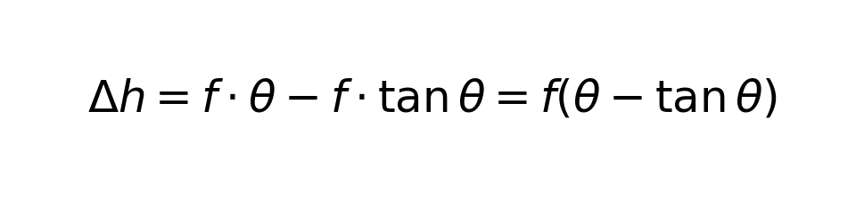
where Δh = f·θ − f·tanθ is the difference between the F-Theta target image height and the ordinary tangent image height (θ in radians, Δh<0), whose absolute value is the barrel (negative) distortion to be introduced. This is the core formula of F-Theta design – distortion is not a defect but the design goal. [(Arizona Optics: Design of Large Working Area F-Theta Lens)](https://wp.optics.arizona.edu/alumni/wp-content/uploads/sites/113/2023/06/msreport-gong-chen.pdf)
In real products, F-Theta linearity error (residual distortion) is expressed by:

High-end industrial F-Theta lenses can reach linearity error <0.1%, mainstream commercial products are generally <0.3% to <1.5% (different wavelength versions of the same series also differ; refer to the manufacturer’s spec sheet), and a relative deviation below 0.5% satisfies most marking requirements. [(Thorlabs: F-Theta Scan Lenses)](https://www.thorlabs.com/NewGroupPage9_PF.cfm?ObjectGroup_ID=6430)
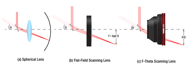
Figure 4 F-Theta distortion principle: y = f·θ vs y = f·tanθ comparison
Source: Thorlabs (China)
2.4 Reverse Telephoto Structure – The Secret of Long Working Distance
Industrial F-Theta scan lenses widely adopt a reverse telephoto (inverted telephoto) structure: the front group is a negative-power lens, the rear group a positive-power lens. The negative group first diverges the beam, and the positive group refocuses it.
The key effect of this structure: the system’s second principal point shifts backward, even beyond the last lens element, making the working distance (last surface to focal plane) much larger than the effective focal length.
The reverse telephoto structure’s working-distance factor (WD/EFL, here the telephoto ratio, note the difference from the photographic definition) is typically about 1.0-1.25, i.e. the working distance is about 1.0-1.25 times the focal length; some models have a working distance slightly less than the focal length. That is why a scan lens with a nominal 160 mm focal length can have an actual working distance of over 180 mm.
Meaning for user selection: never equate focal length with working distance; the equipment Z-axis mounting height must be based on the flange focal length, not the nominal focal length. [(CASTech: F-theta Lens Technical Principles)](https://www.castech.com/news_detail/24.html)
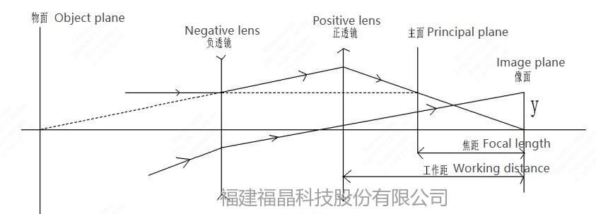
Figure 5 Optical schematic of the reverse telephoto (inverted telephoto) structure
Source: CASTECH
2.5 The Critical Role of Entrance Pupil Position
A scan lens’s entrance pupil is the effective aperture position where the beam enters the lens. In a galvanometer scanning system, the galvo must be placed near the entrance pupil, otherwise large-angle scanning produces vignetting – edge rays are blocked by the barrel or aperture stop, causing power loss at the field edge, larger spots, and degraded image quality. [(RP Photonics: Scanning Lenses)](https://www.rp-photonics.com/scanning_lenses.html)
In a dual-galvo (X-Y galvo) system, the entrance pupil should lie between the two galvos, and the spacing should be minimised to match the entrance pupil position. The larger the galvo spacing, the farther from the design entrance pupil and the more pronounced the vignetting.
The entrance pupil diameter is not the larger the better either – the incident beam diameter and entrance pupil diameter must be properly matched. Generally the incident beam diameter should be 55%-70% of the entrance pupil diameter (ratio about 0.55-0.7), leaving enough spot-offset margin during scanning.
2.6 Thermal Lensing – The Hidden Killer in High-Power Applications
In kilowatt-class high-power laser applications, even high-transmittance optical elements generate heat from intrinsic material absorption and coating absorption, causing thermal lensing.
Consequences of thermal lensing:
- Focal shift: after heating, the refractive-index distribution changes, the equivalent optical power changes, and the focus position drifts
- Beam quality degradation: thermally induced refractive-index gradients introduce additional aberrations, enlarging the spot and lowering energy density
- Field curvature change: thermal effects are nonuniform across the field, degrading flat-field correction
Mitigation measures:
- Use fused silica material – lower absorption, smaller thermal expansion coefficient, far better thermal stability than ordinary optical glass
- Optimise low-absorption coating design to reduce coating heating
- Appropriately lower power density or increase cooling
For continuous fibre laser welding systems, thermal lensing is a factor that must be considered, which is why high-power welding scan lenses must use silica material. [(RP Photonics: Scanning Lenses)](https://www.rp-photonics.com/scanning_lenses.html)
III. Structure and Classification: Four Mainstream Scan Lens Types
3.1 Comprehensive Comparison of Four Types
Along the two dimensions of telecentricity and achromatic capability, scan lenses fall into four main types. This is the first major category to determine when selecting.
| Type | Telecentric angle | Achromatic band | F-Theta distortion | Spot uniformity | Price multiplier | Typical application |
|---|---|---|---|---|---|---|
| Standard F-Theta scan lens | 4°~17° | Single wavelength | <0.5%~<1% | Average, slightly larger at edge | 1× | General marking, engraving |
| Telecentric F-Theta scan lens | <4° (high-end <2°) | Single wavelength | <0.1% | Excellent, uniform across field | 2~5× | Precision cutting, drilling, micromachining |
| Achromatic F-Theta scan lens | 4°~17° | Dual/triple wavelength | <0.5% | Average | 1.3~2× | Multi-wavelength systems, general coaxial vision |
| Telecentric achromatic F-Theta scan lens | <4° (high-end <2°) | Dual/triple wavelength | <0.1% | Best | 3~10× | Precision coaxial vision, semiconductor micro-welding |
Table: Comprehensive comparison of four F-Theta scan lens types. Price multiplier uses a standard F-Theta of the same focal length as the baseline (1×). [(Soar Laser: Scan Lens Selection Guide)](https://www.soar-laser.cn/en/field-lens-selection-guide/) [(Soar Laser: Telecentric Achromatic Scan Lens Selection Guide)](https://www.soar-laser.cn/en/telecentric-achromatic-f-theta-lens-guide/)
3.2 Physical Explanation of Telecentric Scanning Lenses
Telecentric design is an advanced feature of scan lenses; its core is image-space telecentricity: the exit pupil is at infinity, and all chief rays across the field are perpendicular to the image plane (work plane).
In a standard F-Theta scan lens:
- Centre field: beam enters vertically → circular spot ✓
- Edge field: beam enters obliquely → elliptical spot ✗, and the spot becomes larger
Telecentric scan lenses, through special optical design (usually requiring more elements and larger aperture), ensure chief rays at all fields enter the work plane perpendicularly, bringing these benefits:
- Consistent spot shape: circular spots across the field, no ellipticity
- Consistent spot size: uniform spot size from centre to edge, consistent line width/depth
- High cut-edge perpendicularity: straight drilled walls, perpendicular cut cross-sections
- Insensitive to workpiece height variation: small impact from dimensional changes in the depth-of-focus direction
The cost of telecentricity: requires larger front-element aperture, more lens elements, more complex assembly, so it is bulky, heavy, and costly (typically 2-10 times a standard scan lens of the same focal length). The field is also limited by lens aperture; at the same aperture, a telecentric lens has a smaller field. [(RP Photonics: Telecentric Lenses)](https://www.rp-photonics.com/telecentric_lenses.html)
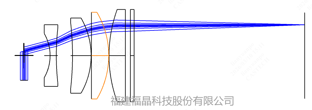
Figure 6 Telecentric scanning lens principle: standard scan lens oblique edge incidence vs telecentric perpendicular full-field incidence
Source: CASTECH
3.3 Principles and Difficulties of Achromatic Scan Lenses
Chromatic aberration arises because different wavelengths have different refractive indices in the same glass, leading to different focus positions. For multi-wavelength laser systems or coaxial vision systems, this is a fatal problem – for example, the 650 nm red-light vision focus and the 1064 nm laser focus may differ by several millimetres after passing through a standard scan lens.
The principle of achromatic design: by combining glasses with different dispersion characteristics (e.g. crown + flint glass) and exploiting the differences in their dispersion curves, the foci of two or more design wavelengths coincide.
Selection points for achromatic scan lenses:
- Not the wider the better: the wider the coating band, the more coating layers stacked (from a few to tens of microns), the greater the internal stress, the easier to delaminate, the lower the transmittance, and the higher the cost
- Typical configuration: 532 nm ±15 nm + 1064 nm ±30 nm (dual wavelength), or 1064 nm + 650 nm (coaxial vision)
- Dual-band achromatic scan lenses cost 30%-50% more than single-band
- Femtosecond lasers require broadband achromatic design to compensate for dispersion and spot broadening caused by the broad spectrum
Actual selection should choose a product that just covers your wavelengths, not pursue “all-band universal” – the price of all-band compatibility is lower transmittance, reduced coating reliability, and sharply higher cost. [(Soar Laser: Telecentric Achromatic Scan Lens Selection Guide)](https://www.soar-laser.cn/en/telecentric-achromatic-f-theta-lens-guide/)
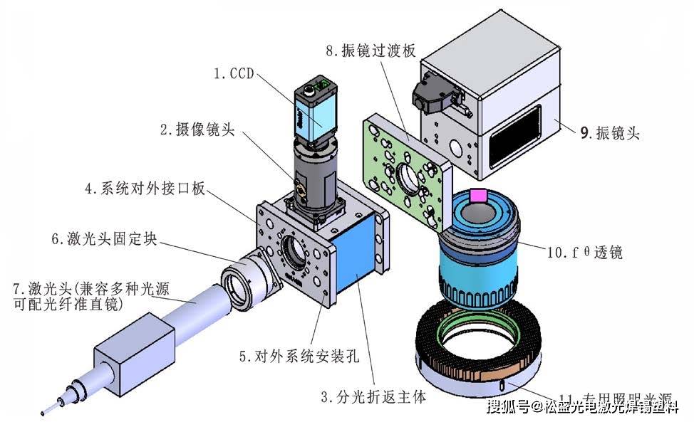
Figure 7 Coaxial vision optical path: laser and visible light share one scan lens for confocal operation
Source: Sohu Tech
3.4 Classification by Structural Type
| Structure type | Number of elements | Features | Applicable scenario |
|---|---|---|---|
| Single-element | 1 element | Simplest structure, lowest cost, large field curvature and aberrations | Small-field low-precision applications, simple CO₂ processing |
| Air-gap type | 2-3 elements | Mainstream industrial design, air spacing aids heat dissipation, better aberration correction | General marking, engraving, general welding |
| Multielement complex type | 3-7 elements | High precision, large field, telecentric design, thorough aberration correction | Precision machining, telecentric lenses, achromatic lenses |
| Aspheric type | Fewer (with aspheric) | Fewer elements for better correction, compact, difficult to fabricate | High-end scan lenses, miniaturized systems |
Table: Comparison of scan lenses by structural type. Industrial F-Theta lenses are mainly 2-3 element air-gap designs, e.g. Thorlabs FTH series uses 2 or 3 air-spaced elements. [(Thorlabs: F-Theta Scan Lenses)](https://www.thorlabs.com/NewGroupPage9_PF.cfm?ObjectGroup_ID=6430)
In high-end F-Theta designs, the aspheric surface sag equation is:
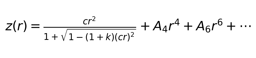
where z is the surface sag, r is the radial coordinate, c is the vertex curvature (c = 1/R, R the vertex radius of curvature), k is the conic constant, and A₄/A₆ are higher-order aspheric coefficients. Aspherics offer more design freedom than spheres, achieving better aberration correction with fewer elements.
3.5 Classification by Material
| Material | Applicable wavelength | Damage threshold | Thermal stability | Price | Typical application |
|---|---|---|---|---|---|
| Optical glass (K9, etc.) | Visible to near-IR | Low to medium | Average | Low | Low-power marking (20-50 W) |
| Fused silica | UV to near-IR | High (~5 J/cm² @10 ns) | Excellent | High | High-power welding, ultrafast lasers, UV processing |
| Zinc selenide (ZnSe) | 10.6 um (CO₂) | Medium | Average | High | CO₂ laser processing |
| Silicon (Si) / Germanium (Ge) | Mid to far IR | Medium | Average | Medium-high | Special IR laser applications |
Table: Comparison of four scan lens materials. Damage thresholds reference Thorlabs FTH series: 5 J/cm² (1064 nm, Ø1 mm, 10 ns, 10 Hz). [(Thorlabs: F-Theta Scan Lenses)](https://www.thorlabs.com/NewGroupPage9_PF.cfm?ObjectGroup_ID=6430)
IV. Key Parameter Interpretation (Technical Selection Level)
The following are all core parameters that must be mastered when selecting scan lenses, each with a definition/formula and clear selection significance, covering a complete parameter system from entry to expert level.
| Parameter name | Definition / formula | Selection significance |
|---|---|---|
| 1. Effective Focal Length (EFL) | Distance from the system’s second principal point to the focal plane. The core parameter determining scan field and spot size. Common specs: F63, F80, F100, F160, F210, F254, F300, F330, F420. | Focal length ↑ → field ↑, spot ↑, depth of focus ↑. A trade-off between processing range and precision. Short focal length = small spot + high precision but small range; long focal length = large range but lower precision. |
| 2. Scan field | The effective processing area a scan lens can cover, usually expressed as the side length of a square.

Empirical formula: field ≈ 0.7 × focal length (coefficient about 0.65-0.80 depending on max scan angle, larger for short focal length models) |
The first selection metric. In practice leave 10-20% margin; over-field use causes sharply increased edge aberrations, spot deformation, and power drop. |
| 3. Focused spot diameter |
Diffraction-limited formula (Gaussian beam): 
(1/e² spot diameter) M² = beam quality factor, λ = wavelength, f = focal length, D = incident beam diameter Geometric imaging formula (fibre coupling): 
d_fiber = fibre core diameter, f_f = scan lens focal length, f_c = collimator focal length |
Determines processing line width/precision and energy density. Smaller spot = more concentrated energy, finer processing. To get a small spot: short focal length + large incident beam + short wavelength + good beam quality (M² near 1). |
| 4. Depth of Focus / Rayleigh Length |
Depth of focus = 2 × Rayleigh length 
Within the depth of focus the spot diameter varies by no more than √2. By this diffraction definition, F160 depth of focus is only about 0.5 mm, F330 about 2 mm (M²=1, D=12 mm); actual welding tolerance must also add workpiece and alignment errors – do not overestimate long depth-of-focus margin. |
Determines tolerance to workpiece height variation. Large depth of focus → friendly to thick-plate welding, but larger spot; shallow depth of focus → fine thin-plate processing, but sensitive to Z-axis height. An important vertex of the focal-length–spot–depth triangle. |
| 5. Entrance pupil diameter | The maximum incident beam diameter a scan lens can accept. Common specs: 10 mm, 12 mm, 14 mm, 15 mm, 20 mm, 30 mm. | Must be ≥ the galvo spot. Insufficient entrance pupil → vignetting → edge power loss, larger spot. A larger entrance pupil allows a thicker incident beam and a smaller focused spot, but also a larger lens and higher cost. |
| 6. Entrance pupil position | Distance from the entrance pupil (image of the aperture stop) to the first lens surface of the scan lens. | Often overlooked but extremely important. The galvo must be near the entrance pupil; in dual-galvo systems the entrance pupil lies between the two galvos. Mismatch → large-angle vignetting. Mounting spacing must match the design value. |
| 7. Scan angle | The maximum beam deflection angle allowed by the scan lens. Common specs: ±11°, ±14.8°, ±15°, ±17.3°, ±20°, ±25°, ±28°. | The galvo swing angle must be ≤ the lens’s allowed scan angle; mismatch means the actual field is smaller than nominal. Large-angle lenses provide a larger field at the same focal length, or allow a shorter focal length (smaller spot) at the same field. |
| 8. F-Theta Distortion (Linearity Error) |
Expressed as the percentage deviation of actual image height from the ideal linear position |
Determines the geometric accuracy of marked patterns. High-end products <0.1%, standard products <0.5% to <1%. High-precision applications (PCB drilling, QR code marking) demand tight distortion. |
| 9. Telecentric angle | The angle between the exit chief ray and the optical axis (normal) at the edge field. Standard scan lenses 4°-17°, telecentric <4°, high-end telecentric <2°. | Smaller telecentric angle → better spot consistency, higher cut-edge perpendicularity, more accurate vision positioning. Precision cutting/drilling recommends <4°, semiconductor micro-welding/high-end vision recommends <2°. Higher telecentricity → larger, more expensive lens. |
| 10. Working Distance (WD) | Distance from the last optical surface of the scan lens to the focal plane. F-Theta lenses use a reverse telephoto structure, so working distance is often slightly larger than or close to the focal length (WD/EFL about 1.0-1.25). | Affects equipment Z-axis space and fixture design. Note: working distance ≠ focal length ≠ flange focal length. A long working distance eases installation of air-blowing devices and protective windows, but the lens is longer and more expensive. |
| 11. Flange Focal Length (FFL) | Distance from the mounting flange face to the focal plane. More meaningful for engineering than working distance. | A key parameter for equipment installation design; directly determines the total height from the galvo mounting face to the workpiece surface. When selecting, always verify the match between flange focal length and equipment column height. |
| 12. Laser-Induced Damage Threshold (LIDT) | The maximum laser power density / energy density the lens can withstand. Pulsed lasers focus on J/cm², CW lasers on W/cm². Typical value: silica material about 5 J/cm² (1064 nm, 10 ns, 10 Hz). | Must be considered for high-power / short-pulse applications. Insufficient damage threshold → coating burn, lens damage. Silica is far superior to ordinary optical glass. Must be converted for actual use conditions (different pulse width, frequency, spot size require conversion). |
| 13. Applicable wavelength | The wavelength range for which the coating and aberration correction are optimised. Common: 1064 nm, 532 nm, 355 nm, 10.6 um. Achromatic lenses cover 2-3 bands. | Must strictly match the laser wavelength. Mismatch → sharp transmittance drop, poor focusing, possible coating damage. Achromatic lenses are not the wider the better; choose one that just covers your wavelengths. |
| 14. Spot uniformity | Consistency of spot size, shape, and energy distribution at all positions across the field. Depends on the level of aberration correction. | Directly affects processing consistency. Telecentric design significantly improves uniformity. Additive manufacturing and large-area marking demand high uniformity. |
EOF
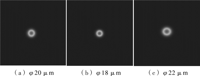
Figure 8 Measured curves of field curvature and F-Theta distortion
Source: Applied Optics (journal paper)
V. Typical Applications and Selection Methodology
5.1 Comparison of Selection Parameters Across Four Major Application Scenarios
Different application scenarios have vastly different requirements for scan lenses. The following is a comparison of selection parameters for four typical laser processing scenarios:
| Parameter dimension | Laser marking / engraving | Laser welding | Precision cutting / drilling | Precision scribing / micromachining |
|---|---|---|---|---|
| Scan lens type | Standard F-Theta | Standard / telecentric F-Theta (silica) | Telecentric F-Theta | Telecentric achromatic F-Theta |
| Focal length range | F100~F330 | F160~F420 | F63~F160 | F63~F100 |
| Spot requirement | Medium (20-50 um) | Large (50-200 um) | Small (10-30 um) | Ultra-small (<10 um) |
| Depth of focus requirement | Low to medium | High (thick plate needs long depth) | Medium | Low |
| Telecentricity | Average | Medium to high | High (<4°) | Very high (<2°) |
| Material | Optical glass / silica | Fused silica | Fused silica | Fused silica |
| Power level | 20~100W | 500W~6kW | 10~500W | 1-50 W (UV / ultrafast) |
| Distortion requirement | <0.5%~<1% | <0.5% | <0.1% | <0.05% |
| Core selection conflict | Field vs precision | Spot vs depth of focus | Field vs telecentricity | Wavelength range vs achromatic precision |
Table: Comparison of scan lens selection parameters across four application scenarios. Combined source: [(Soar Laser: 5 selection guides)](https://www.soar-laser.cn/en/field-lens-selection-guide/)
5.2 Selection Method One: Laser Marking – Focal Length + Field + Wavelength Matching Method
Laser marking is the largest-volume scan lens scenario, suited to optical systems with near-collimated light incidence (Q-switched / MOPA / CO₂ RF tube lasers, etc.).
Optical path: laser → beam expander → galvo → scan lens → workpiece
Selection steps (six-step method):
- Determine wavelength – determine the lens coating band from the laser type. 1064 nm (fibre) / 355 nm (UV) / 532 nm (green) / 10.6 um (CO₂), must match strictly.
- Determine processing field – based on the largest workpiece size, add 10-20% margin. Field ≈ 0.7 × focal length (coefficient about 0.65-0.80 depending on max scan angle), invert to get required focal length.
- Verify spot precision – use the diffraction limit formula to check whether the target line width is achievable at that focal length: d = 4·M²·λ·f/(π·D). If the spot is too large, increase the incident beam diameter (larger expansion ratio) or shorten the focal length.
- Match entrance pupil to galvo – the lens entrance pupil must be clearly larger than the galvo spot: in practice the incident beam diameter should be 55%-70% of the entrance pupil (entr pupil about 1.4-1.8 times the beam), leaving enough spot-offset margin.
- Match scan angle – galvo swing angle ≤ lens allowed scan angle, otherwise the actual field falls short of nominal.
- Confirm working distance / flange focal length – verify compatibility with equipment column height and workpiece fixture space.
Quick reference table of common focal length specs (1064 nm, theoretical diffraction limit, 12 mm incident spot):
| Focal length | Scan field | Theoretical diffraction spot (1/e², M²=1) | Working distance (approx.) | Recommended column height | Typical application |
|---|---|---|---|---|---|
| F63 | 50×50mm | ~7μm | ~80mm | 300mm | Ultra-fine marking, micromachining |
| F100 | 70×70mm | ~12μm | ~120mm | 350mm | Small-field fine marking |
| F160 | 110×110mm | ~19μm | ~180mm | 400mm | Standard marking (most common) |
| F210 | 150×150mm | ~25μm | ~240mm | 500mm | Medium-field marking |
| F254 | 175×175mm | ~30μm | ~280mm | 550mm | Medium-large field marking |
| F330 | 220×220mm | ~40μm | ~380mm | 650mm | Large-field marking |
| F420 | 300×300mm | ~50μm | ~480mm | 750mm | Ultra-large field applications |
Table: Quick reference of common F-Theta scan lens specs (1064 nm, 12 mm incident spot, estimated by ideal fundamental mode M²=1 diffraction limit). Real lasers often have M² of 1.2-1.5, so the real spot should be calculated by d=4·M²·λ·f/(π·D) with measured M², usually 20%-50% larger than the theoretical values here; manufacturer specs (e.g. Thorlabs FTH160 lists 26 um) also include beam truncation/fill-aperture differences, so refer to the spec sheet; the “recommended column height” is an empirical reference, follow the actual mechanical drawing. Data: [(Soar Laser: Scan Lens Selection Guide)](https://www.soar-laser.cn/en/field-lens-selection-guide/) [(Thorlabs: F-Theta Scan Lenses)](https://www.thorlabs.com/NewGroupPage9_PF.cfm?ObjectGroup_ID=6430)
5.3 Selection Method Two: Galvo Welding Scenario – Hierarchy Method + Triangle Balance Method
Galvo welding is the fastest-growing scan lens application in recent years, with an optical structure and selection logic completely different from marking systems.
Optical path: laser → QBH/IQB → collimator → galvo → scan lens → workpiece
Core difference: the continuous fibre laser used in welding outputs divergent light (point source) and must pass through a collimator to become parallel light; the pulsed laser used in marking outputs near-collimated light. The two spot calculation formulas are completely different and must not be mixed!
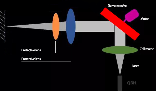
Figure 9 Galvo welding optical path: QBH→collimator→galvo→scan lens→workpiece
Source: PESLASER
5.3.1 Hierarchy Method – Order Cannot Be Reversed
A galvo welding system has a strict hierarchy that must be followed in order during selection:
Scan lens entrance pupil ≥ galvo spot ≥ collimated beam diameter D
4 must-know parameters (confirm before selection):
- Laser NA value (usually 0.11, some 0.22)
- Fibre core diameter (25 um / 50 um / 100 um, etc.)
- Collimator focal length (75 mm / 100 mm / 150 mm, etc.)
- Target scan lens focal length (marking commonly F160 / F210 / F254 / F420, welding also has long-focal specs like F380)
2 core formulas:

where f_c = collimator focal length, f_f = scan lens focal length, NA = fibre numerical aperture, d_fiber = fibre core diameter.
Calculation order (absolutely cannot be reversed):
- First compute D = 2 × f_c × NA
- Determine galvo spot from D (D>20 mm requires a 30 mm galvo)
- Select scan lens entrance pupil from galvo spot (lens pupil ≥ galvo spot)
- Finally select focal length and compute focused spot d = d_fiber × f_f / f_c
⚠️ Common mistake: selecting the focal length first and then matching the galvo and entrance pupil, only to find the pupil insufficient and the galvo cannot fit, wasting much time and money.
5.3.2 Focal Length – Spot – Depth Triangle Balance Rule
The core of welding scan lens selection is finding balance among focal length, spot, and depth of focus, whose relations can be summarised as:
| Focal length change | Spot size | Energy density | Depth of focus | Splatter | Suitable scenario |
|---|---|---|---|---|---|
| Short focal length (F160) | Small | High | Shallow | Much | Thin-plate welding, fine welding |
| Medium focal length (F254) | Medium | Medium | Medium | Medium | Medium-thickness plate, general welding |
| Long focal length (F420) | Large | Low | Deep | Little | Thick-plate welding, deep-penetration welding |
Table: Focal length – spot – depth triangle relationship. Core rule: focal length ↑ → spot ↑ → depth of focus ↑, the three trade off against each other. [(Soar Laser: Galvo Welding Scan Lens Selection)](https://www.soar-laser.cn/%e6%8c%af%e9%95%9c%e7%84%8a%e6%8e%a5%e6%80%8e%e4%b9%88%e9%80%89%e5%9c%ba%e9%95%9c%ef%bc%9f%e7%84%a6%e8%b7%9d%e3%80%81%e5%85%89%e6%96%91%e3%80%81%e7%84%a6%e6%b7%b1%e4%b8%89%e7%82%b9%e5%b9%b3%e8%a1%a1/)
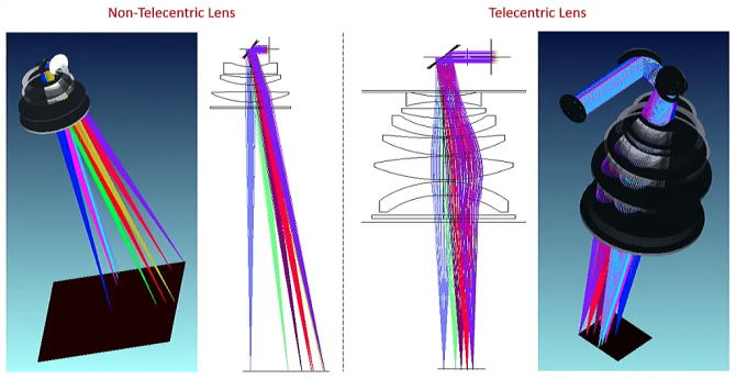
Figure 10 Achromatic telecentric F-Theta scan lens dual-wavelength optical path comparison
Source: Astron Japan (Ronar-Smith®)
5.3.3 Special Requirements for Welding Scan Lenses
- Must use silica material: ordinary optical glass has severe thermal lensing at kilowatt power
- High damage threshold required: energy at the high-power-density focal point is enormous
- Larger entrance pupil usually: welding collimated beam diameter often reaches 20-30 mm
- High thermal stability required: long continuous operation, focus drift must be small
- Protective window essential: severe welding spatter requires a replaceable protective window
5.4 Selection Method Three: Coaxial Vision Precision Machining – Telecentric Achromatic Selection Method
A coaxial vision system is the most typical application of telecentric achromatic scan lenses. Wherever the laser shoots, the camera “looks,” achieving “what you see is what you get” high-precision machining.
Core selection points:
- Band matching (step one) – confirm both laser and vision wavelengths are within the lens band. Typical configs: 1064 nm+650 nm, 532 nm+650 nm, 355 nm+650 nm.
- Telecentricity grade selection – choose grade by positioning accuracy:
- general vision positioning: telecentric angle <4° is enough
- high-precision vision alignment (±0.02 mm): telecentric angle <2°
- semiconductor micro-welding (±0.01 mm): telecentric angle <1° (custom grade)
- Focal length vs field matching – select focal length by processing field. At the same entrance pupil, focal length ↑ → working distance ↑ → field ↓.
- Field margin – recommend field 20%-30% larger than processing need, to avoid edge quality degradation.
- Transmittance requirement – UV/green band >90%, IR band >95%.
- Working distance confirmation – match the vision system focal length, ensure laser focus and vision focus are coplanar.
Telecentricity grade classification and application correspondence:
| Grade | Telecentric angle range | Spot consistency | Typical positioning accuracy | Price multiplier | Typical application |
|---|---|---|---|---|---|
| Standard grade | 4°~17° | Noticeably larger at edge | ±0.1 mm and above | 1× | General marking, rough positioning |
| Standard telecentric | <4° | Basically uniform across field | ±0.03~0.05mm | 2~5× | Precision marking, 3C electronics vision positioning |
| High-end telecentric | <2° | Highly uniform across field | ±0.01~0.02mm | 5~10× | Semiconductor micro-welding, PCB drilling |
| Custom telecentric | <1° | Near-diffraction-limit uniform | ±0.005mm | 10×+ | MEMS, wafer-level processing |
Table: Telecentricity grade classification and application correspondence. Price multiplier uses a standard F-Theta of the same focal length as the baseline. [(Soar Laser: Telecentric Achromatic Scan Lens Selection Guide)](https://www.soar-laser.cn/en/telecentric-achromatic-f-theta-lens-guide/) [(RP Photonics: Telecentric Lenses)](https://www.rp-photonics.com/telecentric_lenses.html)
5.5 Selection Parameter Priority Matrix
Different application scenarios have different parameter priorities. The following matrix helps you quickly judge which parameters are “must-satisfy” and which are “can-compromise”:
| Parameter | Marking / engraving | Galvo welding | Precision cutting / drilling | Coaxial vision | Additive manufacturing |
|---|---|---|---|---|---|
| Wavelength matching | ★Must | ★Must | ★Must | ★Must | ★Must |
| Focal length / field | ★Must | ★Must | ★Must | ★Must | ★Must |
| Entrance pupil diameter | ★Must | ★Must | ★Must | ☆Important | ★Must |
| Spot size | ☆Important | ★Must | ★Must | ☆Important | ☆Important |
| Depth of focus | ○Reference | ★Must | ☆Important | ○Reference | ☆Important |
| Telecentricity | ○Reference | ☆Important | ★Must | ★Must | ☆Important |
| Distortion | ☆Important | ○Reference | ★Must | ☆Important | ☆Important |
| Damage threshold | ○Reference | ★Must | ☆Important | ○Reference | ☆Important |
| Achromatic | ○Reference | ☆Important | ○Reference | ★Must | ○Reference |
| Working distance | ☆Important | ☆Important | ☆Important | ☆Important | ★Must |
Table: Selection parameter priority matrix. ★Must = cannot be used normally if unsatisfied; ☆Important = affects performance and quality; ○Reference = better to have, acceptable without.
VI. In-Depth Analysis of Scan Lens Characteristics
6.1 Applicability Boundaries of Spot Size Formulas
Many people know only one spot formula, but in fact different optical systems require completely different spot calculation formulas; using the wrong formula causes serious selection errors.
| Formula type | Formula | Applicable scenario | Prerequisite | Accuracy |
|---|---|---|---|---|
| Diffraction-limited formula (ideal Gaussian) |
d = 4λf/(πD) | Theoretical calculation, ideal TEM₀₀ beam | M²=1, perfect beam quality, no aberration | Theoretical limit, actually larger |
| Gaussian spot formula with M² factor |
d = 4·M²·λ·f/(π·D) | Near-collimated incidence systems (marking / Q-switching / MOPA) | Incident near-collimated Gaussian beam, M² known | Fairly high, close to reality |
| Geometric imaging formula (fibre coupling) |
d = d_fiber × f_f / f_c | Fibre output + collimator system (continuous laser welding) | Fibre imaging system, geometric optics approximation | High, very accurate in engineering |
Table: Applicability comparison of three spot size formulas. Marking systems use the Gaussian formula with M², welding systems use the geometric imaging formula; the two must never be mixed. [(Soar Laser: Ultimate F-Theta Scan Lens Selection Guide)](https://www.soar-laser.cn/en/f-theta-lens-selection-guide/)
6.2 Marking System vs Welding System Scan Lens Selection Differences
These are the two most easily confused application scenarios and a hot spot for selection errors.
| Comparison dimension | Marking system (path A) | Welding system (path B) |
|---|---|---|
| Laser type | Q-switched / MOPA / CO₂ RF tube / green / UV solid-state | Continuous fibre laser (with QBH/IQB interface) |
| Laser output state | Near-collimated light (with internal collimation) | Divergent light (fibre point-source output) |
| Optical path structure | Laser → beam expander → galvo → scan lens → workpiece | Laser → collimator → galvo → scan lens → workpiece |
| Spot calculation formula | Diffraction-limited formula (with M² factor) | Geometric imaging formula (fibre amplification) |
| Scan lens material | Optical glass or silica (glass OK at low power) | Must be fused silica (high power + thermal lensing) |
| Typical power level | 20W ~ 100W | 500W ~ 6000W |
| Typical entrance pupil spec | 10~15mm | 20-30 mm (or larger) |
| Core selection logic | Field-precision balance | Spot-depth-penetration balance |
| Interchangeable? | Marking lens cannot be used for welding (insufficient damage threshold, large thermal drift) | Welding lens can be used for marking (over-performance, high cost) |
Table: Marking vs welding system scan lens selection differences. The two have completely different optical structures and formula systems – the first prerequisite to clarify when selecting. [(Soar Laser: Ultimate F-Theta Scan Lens Selection Guide)](https://www.soar-laser.cn/en/f-theta-lens-selection-guide/) [(Soar Laser: Galvo Welding Scan Lens Selection)](https://www.soar-laser.cn/%e6%8c%af%e9%95%9c%e7%84%8a%e6%8e%a5%e6%80%8e%e4%b9%88%e9%80%89%e5%9c%ba%e9%95%9c%ef%bc%9f%e7%84%a6%e8%b7%9d%e3%80%81%e5%85%89%e6%96%91%e3%80%81%e7%84%a6%e6%b7%b1%e4%b8%89%e7%82%b9%e5%b9%b3%e8%a1%a1/)
6.3 Special Requirements for Femtosecond Laser Scan Lenses
Femtosecond lasers (pulse width on the order of 10^-15 s) have extremely short pulse durations and very broad spectral widths (a few nm to tens of nm), imposing special requirements on scan lenses:
- Broadband achromatic: uniform focusing over a broad spectrum, avoiding spot and pulse broadening from dispersion
- Fused silica material: high damage threshold, low nonlinear effects
- Low group-delay dispersion (GDD): reduces pulse broadening during propagation in media
- High laser damage threshold: femtosecond peak power is extremely high, easily causing dielectric breakdown
A standard F-Theta scan lens cannot focus uniformly over a broad spectrum, causing dispersion, larger spots, and lower peak energy density; a specialised achromatic design is required. [(CASTech: F-theta Lens Technical Principles)](https://www.castech.com/news_detail/24.html)
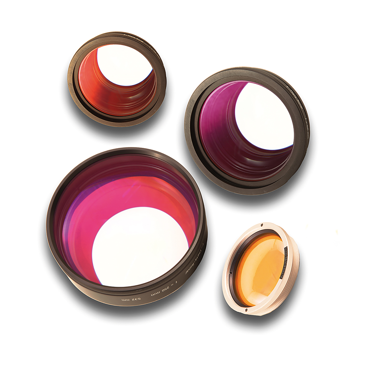
Figure 11 Industrial F-Theta scan lens product series
Source: SCANLAB (Germany)
VII. Common Misconceptions (12, with Comparison Table)
The following are the 12 most common misconceptions in scan lens selection and use; almost every practitioner has encountered at least half of them.
| No. | Common misconception | Truth | Correct practice |
|---|---|---|---|
| 1 | “A flat-field lens is an F-Theta scan lens” | A flat-field lens is the broad concept; F-Theta is a subclass of flat-field lenses, like the relation between “fruit” and “apple.” Flat-field lenses also include photographic flat-field lenses, microscope flat-field objectives, standard flat-field scanning lenses, etc. | When selecting, specify clearly “F-Theta flat-field scanning lens” to avoid ambiguity. |
| 2 | “The longer the focal length the better; the larger the field the better” | The cost of a longer focal length is a proportionally larger spot. The F330 spot is about 3.3 times that of F100. If a 0.1 mm line width is required, a large-focal-length lens may not achieve it at all. | Find a balance between processing range and precision; adequate is enough, do not blindly pursue large field. |
| 3 | “A flat-field lens works for all wavelengths” | A scan lens coating and aberration correction are optimised for specific wavelengths. Using a 1064 nm lens with 355 nm UV light not only gives poor focus quality but may burn the coating. | Must select a scan lens exactly matching the laser wavelength. |
| 4 | “F-Theta distortion is bad; the smaller the better” | An F-Theta lens deliberately introduces barrel distortion to cancel tangential nonlinearity – this is “useful distortion.” What must be controlled is residual linearity error, not reducing distortion to zero – if distortion were truly zero it would degrade to a standard flat-field lens. | Focus on the linearity error (F-Theta distortion) metric, not the presence of distortion. |
| 5 | “A flat-field lens is similar to a focusing lens and they are interchangeable” | A focusing lens is a single-point focusing element (1-2 elements) designed for a fixed direction; a flat-field scanning lens is a complex multielement system designed for large-angle scanning. Mixing them is like using a magnifying glass as a camera lens. | Scanning systems must use an F-Theta scan lens; fixed optical paths use a focusing lens. |
| 6 | “A flat-field lens can be used beyond its rated field indefinitely” | Beyond the nominal field, aberrations rise sharply, the spot deforms severely, and energy density plunges. Over-field use not only gives poor results but may damage the lens. | Use strictly within the nominal field; recommend leaving 10-20% margin. |
| 7 | “The entrance pupil only needs to be larger than the spot” | The entrance pupil must not only exceed the spot diameter but also account for spot offset from scan angle. In dual-galvo systems the entrance pupil diameter should be clearly larger than the incident beam diameter (ratio about 1.4-1.8). Insufficient pupil margin → large-angle vignetting → larger edge spots, lower energy. | Scan lens entrance pupil ≥ galvo spot, with sufficient scan-offset margin. |
| 8 | “The wider the coating band the better” | Wider coating → more stacked layers → greater internal stress → easier cracking/delamination → lower transmittance → soaring cost. Real scan lenses usually cover only 2-3 specific bands. | Choose a product covering just your wavelengths; do not pursue “all-band universal.” |
| 9 | “Marking and welding scan lenses are interchangeable” | Marking uses Q-switched/MOPA parallel output, welding uses continuous fibre laser divergent output – completely different optical structures. Welding lenses must withstand higher power, with stricter damage threshold and thermal management requirements, usually silica material. Spot calculation formulas also differ completely. | Welding systems must use dedicated silica welding scan lenses, not standard marking lenses. |
| 10 | “Focal length equals working distance” | Working distance (last surface to focal plane) ≠ focal length (principal point to focal plane). F-Theta lenses use a reverse telephoto structure, so working distance is close to or slightly larger than focal length (WD/EFL about 1.0-1.25, design-dependent). Engineering installation uses flange focal length. | Clearly distinguish EFL (effective focal length), WD (working distance), and FFL (flange focal length) when selecting. |
| 11 | “Software compensation can replace an F-Theta lens” | Software can only compensate position errors of scan nonlinearity, not field curvature, astigmatism, coma, and other aberrations. An F-Theta lens provides not only linear scanning but, more importantly, flat-field focusing and uniform spots across the field – irreplaceable by software. | High-precision, high-quality machining must use an F-Theta lens; software is only auxiliary correction. |
| 12 | “All telecentric scan lenses are the same; the higher the telecentricity the better” | Telecentricity has degrees: standard lenses 4°-17°, telecentric <4°, high-end telecentric <2°. Prices differ greatly between grades (2-10 times). Higher telecentricity → smaller field, larger lens, higher cost. Blindly pursuing high telecentricity is wasteful. | Choose telecentricity grade by actual precision needs; adequate is optimal. |
Table: Comparison table of 12 common misconceptions in scan lens selection. Combined sources: [(Soar Laser: Flat-Field Lens Encyclopedia)](https://www.soar-laser.cn/en/flat-field-lens-encyclopedia/) [(Soar Laser: 5 selection guides)](https://www.soar-laser.cn/en/field-lens-selection-guide/) [(RP Photonics: Scanning Lenses)](https://www.rp-photonics.com/scanning_lenses.html)
VIII. History and Notes
8.1 Brief History of Scan Lens Technology Development
- 19th century: multielement lenses gradually developed; the Petzval portrait lens was an early multielement representative, but its curved focal surface (Petzval curvature) was a clear problem that later flat-field design aimed to solve
- Mid-20th century: with advances in optical design theory and computing power, multielement flat-field objectives were widely used in microscopy
- 1960s: after the laser invention, scanning optics gradually developed; early scanning systems used ordinary spherical lenses, relying on complex mechanical and electronic compensation
- 1970s-80s: F-Theta lens design theory matured, and laser marking systems with galvo scanning began to commercialize
- 1990s: industrial laser marking boomed, F-Theta scan lenses became standard, domestic manufacturers began to follow
- 2000s: advanced products such as telecentric F-Theta and achromatic F-Theta appeared, meeting precision machining needs
- 2010s: high-power fibre laser welding rose, demand for large-entrance-pupil silica F-Theta scan lenses grew rapidly
- 2020s: femtosecond and UV laser micromachining drove high-precision telecentric achromatic lens development, aspheric/freeform technology began to be applied to high-end lens design
8.2 Well-Known Industry Manufacturers
International brands:
- SILL Optics (Germany): a benchmark manufacturer specialising in scan lenses, with authoritative technical data and a complete product line
- Jenoptik (Germany): high-end industrial optical devices, outstanding performance
- Excelitas / DPM Photonics (USA): well known in the CO₂ laser F-Theta field
- Thorlabs (USA): research and small-batch industrial applications, transparent specs and complete documentation
- EKSMA Optics (Lithuania): laser optical components covering many wavelengths
- CASTech (China): a global manufacturer of optical crystals and components
Domestic brands:
- Nanjing Wavelength Opto-Electronic: a leading domestic scan lens designer, complete product line, good value
- Tiankai Optoelectronics (Suzhou): a supplier of galvo + scan lens matching solutions
- Others: numerous optical manufacturers in Shenzhen, Wuhan, Suzhou, etc. offer products at different grades
8.3 Use and Maintenance Precautions
- Installation orientation: scan lenses have a front and back, usually marked “galvo side” and “workpiece side”; reversing them severely degrades imaging quality
- Cleaning and maintenance: when surfaces are contaminated with dust/oil, wipe gently with dedicated lens paper or cloth with isopropyl alcohol; never use ordinary tissue or touch with fingers
- Protective window: in harsh environments such as welding and cutting, a protective window must be added at the work end and replaced regularly
- Thread matching: common thread specs M85×1, M79×1, M102×1, M55×1, etc.; use thread adapters when mismatched
- Storage environment: dry, dust-free, stable temperature; avoid coating moisture and mold
IX. References
- RP Photonics Encyclopedia: Scanning Lenses — Dr. Rüdiger Paschotta
- RP Photonics Encyclopedia: Telecentric Lenses — Dr. Rüdiger Paschotta
- RP Photonics Buyer’s Guide: Purchasing Advisor for Scanning Lenses
- Soar Laser: Scan Lens (F-Theta Lens) Selection Guide
- Soar Laser: Ultimate Guide to Laser Scan Lens Selection: 90% of Equipment Makers Have Hit These Pitfalls
- Soar Laser: How to Select a Scan Lens for Galvo Welding? A Practical Guide to Focal Length, Spot, and Depth Balance
- Soar Laser: How to Choose a Scan Lens for Galvo Welding Systems – Confirm 4 Parameters First, Then Apply 2 Formulas
- Soar Laser: Telecentric Achromatic Scan Lens Selection Guide: Key Technology for Coaxial Vision and Multi-Wavelength Laser Systems
- Thorlabs: F-Theta Scan Lenses
- Thorlabs: F-Theta Lenses Tutorial
- CASTech: F-theta Lens Technical Principles and Selection Guide
- SPIE: Optical design and performance of F-Theta lenses for high-power and high-precision applications (Proc. SPIE 9626, 2015)
- University of Arizona: Design of Large Working Area F-Theta Lens (MS Report, 2023)
- ISO 10110: Optics and photonics — Preparation of drawings for optical elements and systems
- “Principles and Applications of Lasers”, Higher Education Press
- Nanjing Wavelength Opto-Electronic Technology Co., Ltd.: A 355 nm UV telecentric f-theta lens eliminating field curvature and astigmatism (invention patent CN201910268787.2)
Bottom dual modules
Further reading module
📖 Further Reading
- Achromatic Scan Lens Encyclopedia: Dual-Wavelength Confocal and Coaxial Vision F-Theta Lens Selection
- → Beam Expander Encyclopedia: Principles, Parameters, and Selection Guide
- → Focusing Lens Encyclopedia: Spherical / Aspheric / Achromatic Focusing Lenses
- → Beam Shaper Encyclopedia: From Gaussian to Flat-Top Light
- → Telecentric Scanning Lens Encyclopedia
- → Anti-Reflection Coating Principles and Applications: Optical Wisdom Hidden in a 56° Tilt
- Laser Protective Window Encyclopedia: Selection and Materials for Cutting / Welding / Scan Lens / Galvo Protection
Related product recommendation module
🔗 Related Products
- → F-Theta Scan Lenses / Flat-Field Scanning Lenses (complete range of wavelengths and focal lengths)
- → Laser Optical Components (focusing lenses, mirrors, beam expanders, windows, etc.)
- → Galvo Systems (high-speed scanning galvos, welding galvos, coaxial vision galvos)
- → Collimators (fibre laser collimators, multiple focal lengths available)
- → Protective windows (high-power laser protection, imported silica material)
This article was compiled by the technical team of Changsha Soar Laser Equipment Co., Ltd. | Updated: October 16, 2026
Technical consultation: 15927220467 (WeChat same number) | Email: 859818709@qq.com
Leave a Reply