


What Is Polarisation-Maintaining Fibre? How to Stop the Polarisation Drifting
Polarisation-maintaining fibre has a specially designed core that keeps the polarisation state of the input light throughout the transmission. It introduces stress zones on both sides of the core to create a strong birefringence between the two orthogonal directions, which suppresses the energy coupling between the polarisation modes. The sections below cover the birefringence mechanism, the key parameters, the main types and the engineering applications.
Table of contents
- 1. What is polarisation-maintaining fibre? Getting the core concept straight
- 2. Working principle: how polarisation-maintaining fibre is achieved
- 3. Key parameters: reading the specifications of polarisation-maintaining fibre
- 4. Main types: what kinds of polarisation-maintaining fibre are there
- 5. Applications: where is polarisation-maintaining fibre used?
- 6. Common misconceptions: pitfalls to avoid
1. Core concept: what is polarisation-maintaining fibre?
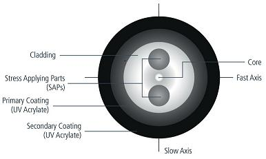
Polarisation-maintaining fibre (PM fibre) is a specially designed single-mode fibre that keeps the polarisation state of the input light while it is transmitted. A standard single-mode fibre also supports two orthogonal polarisation modes, but small irregularities in the core, stress variations and bending keep coupling energy between those two modes, so the output polarisation state changes at random. Polarisation-maintaining fibre introduces a strong birefringence (a difference in refractive index between the two orthogonal polarisation directions) into the core, so that the propagation constants of the two polarisation modes differ substantially and the coupling between them is suppressed. As long as the polarisation of the input light is aligned with one of the principal axes of the fibre, the output polarisation state is essentially unchanged.
2. Working principle: how is polarisation-maintaining fibre achieved?
Stress-induced birefringence vs shape birefringence
Polarisation-maintaining fibre holds the linear polarisation by introducing a strong birefringence, and there are two main mechanisms:
① Stress-induced birefringence: a material with a different thermal expansion coefficient from the silica (such as B₂O₃) is introduced on both sides of the core. While the fibre is drawn and cools, the two stress zones shrink differently from the silica and put a transverse compressive stress on the core. Through the photoelastic effect this stress is converted into a difference in refractive index, that is, into birefringence.
Stress-induced PM fibre is by far the most widely used type, the typical representatives being PANDA (panda type) and bow-tie.
② Shape birefringence: birefringence is introduced through a non-circular core geometry, such as an elliptical core. The birefringence of an elliptical-core fibre comes from the waveguide effect, where the effective refractive index differs between the two orthogonal polarisation directions. Shape birefringence is usually weaker than stress-induced birefringence, but it is much less sensitive to temperature changes.
💡 PANDA vs bow-tie: comparing the two mainstream structures
PANDA fibre: two round stress zones placed symmetrically on both sides of the core, which gives it the look of a panda face. The process is mature, the loss is low, and it is the mainstream polarisation-maintaining fibre. Bow-tie: two wedge-shaped stress zones give a stronger birefringence, but they are harder to manufacture and the loss is slightly higher, so they are used where the polarisation performance must be excellent. The typical beat length of both is in the 2-4 mm range at 1550 nm.
Stress-induced birefringence
is the most common approach. Stress rods with a different thermal expansion coefficient (such as borosilicate glass) are placed in the cladding on both sides of the core, and while the fibre cools after drawing, the rods shrink by different amounts and apply an asymmetric mechanical stress to the core. Through the photoelastic effect the stress makes the refractive index anisotropic, which produces birefringence. The typical stress-induced PM fibres are the PANDA fibre (two round stress rods) and the bow-tie fibre (two wedge-shaped stress regions).
Shape birefringence
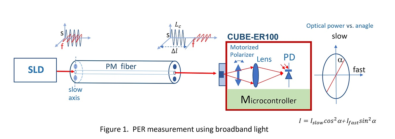
comes instead from making the core elliptical, using the asymmetry of the geometry to produce birefringence. The elliptical-core fibre is the representative of this class, but because its birefringence is usually weaker than the stress-induced type, the stress-induced type is the one used in practice. The figure that assesses the polarisation performance is the polarisation extinction ratio (PER), the ratio of the power polarised along the principal axis to the power polarised along the orthogonal direction after the light has passed through the fibre, expressed in dB. High-quality PM fibres and components reach PER values of 20-30 dB or more.
Beat length
is another important parameter: the transmission length over which the phase difference between the two orthogonal polarisation modes accumulates 2π. The shorter the beat length, the stronger the birefringence. The beat length of a high-birefringence (HiBi) PM fibre is typically in the millimetre range.
3. Key parameters: reading the specifications of polarisation-maintaining fibre
Relation between the beat length and the polarisation extinction ratio
The beat length (L_B) is the intuitive parameter that describes the strength of the birefringence: the length of fibre over which the phase difference between the two orthogonal polarisation modes accumulates 2π. The shorter the beat length, the stronger the birefringence.
L_B = λ / B = λ / (n_x – n_y)
where B is the birefringence strength and n_x – n_y is the difference in refractive index between the two orthogonal directions.
The polarisation extinction ratio (PER) is the key figure for assessing the polarisation performance, defined as the ratio of the power in the main polarisation mode to the power in the orthogonal polarisation mode (in dB). The higher the PER, the purer the polarisation.
PER = 10·log₁₀(P_main / P_cross) [dB]
💡 How the polarisation performance depends on the length
The PER of a PM fibre degrades as the length increases — the longer the fibre, the more opportunities the modes have to couple. Typical values for commercial PM fibres are: above 30 dB over short lengths (metres), about 20-25 dB over a hundred metres, and possibly below 15 dB over a kilometre. PM fibre is therefore used mainly in systems running from a few metres to a few tens of metres.
Core formulas
Modal birefringence: the difference in effective refractive index between the two orthogonal polarisation directions:
B = n_x – n_y
where n_x and n_y are the effective refractive indices along the slow and the fast axis respectively. A typical PM fibre has a B value of about 3×10⁻⁴ to 5×10⁻⁴.
Beat length: the length of fibre over which the phase difference between the two orthogonal polarisation modes accumulates 2π:
L_B = λ / B
For a PM fibre at 1550 nm with B = 4×10⁻⁴ the beat length is about 3.9 mm. The shorter the beat length, the stronger the birefringence and the better the immunity to interference.
Extinction ratio (PER): the key figure for assessing the polarisation performance, defined as the power ratio of the two orthogonal polarisation components (in dB):
PER (dB) = 10 log(P_max / P_min)
High-quality PM fibre components usually reach a PER of 20-30 dB. The longer the fibre, the lower the PER tends to be, because the mode coupling accumulates with the length.
Reading the key parameters is the starting point for assessing the performance of polarisation-maintaining fibre. The table below sets out the main specifications and what they mean:
| Parameter | Meaning | Engineering significance |
|---|---|---|
| Beat length | A parameter that measures the strength of the birefringence; the shorter the beat length, the stronger the birefringence and the better the polarisation performance | It sets how much interference a component can reject, which makes it the first screening figure when a PM fibre is chosen. |
| Polarisation extinction ratio (PER) | The direct indicator of the polarisation performance, in dB, with typical values of 20-30 dB | It directly sets the contrast of the interference fringes: every 1 dB lost in the extinction ratio measurably reduces the visibility. |
| Mode field diameter | Similar to a standard single-mode fibre; it affects the coupling and the connections | Sets the splice loss to other single-mode fibres and the alignment tolerance |
| Cutoff wavelength | The lower wavelength limit that guarantees single-mode operation | The shortest wavelength at which the fibre still operates in a single mode; a PM fibre is normally single-mode as well |
| Transmission loss | The loss of PM fibre is usually slightly higher than in a standard single-mode fibre | The extra loss introduced by the stress zones is usually slightly above that of an ordinary single-mode fibre |
| Stress zone geometry | The diameter and the position of the stress rods in a PANDA fibre | The closer the stress rods sit to the core, the stronger the birefringence, but the harder the alignment and the tighter the bend tolerance become. |
| Principal axis orientation | The azimuth of the fast and the slow axis; it has to be aligned when splicing and coupling | If the principal axis is not aligned with the polarisation of the source the polarisation holding simply fails, which is why the splicer has to be able to align and lock the axis. |
4. Main types: what kinds of polarisation-maintaining fibre are there?
Comparison of the three main types of polarisation-maintaining fibre
| Type | Birefringence mechanism | Typical structure | Characteristics |
|---|---|---|---|
| PANDA (panda type) | Stress-induced birefringence | Round stress applying zones placed symmetrically | The most widely used, low loss, good splicing compatibility |
| Bow-tie | Stress-induced birefringence | Sector-shaped stress zones | Stronger birefringence, but the splicing alignment demands more |
| Elliptical core | Geometrical birefringence | An elliptical core shape | Resists high temperature and is not affected by stress relaxation, but the loss is slightly higher |
A note on how to use polarisation-maintaining fibre: the input light must be injected polarised along one of the principal axes (the fast or the slow axis) if the polarisation state is to be held; injecting at 45° excites both modes and the output polarisation state then varies periodically along the fibre. PM fibre is used mainly in the polarisation-sensitive systems such as fibre interferometers, fibre optic gyroscopes and PM fibre lasers, with typical lengths ranging from a few centimetres to a hundred metres.
Polarisation-maintaining fibre can be classified in many ways, and each dimension helps you understand its characteristics from a different angle. The most common ones are introduced below:
By the mechanism that produces the birefringence
Stress-induced polarisation-maintaining fibre
Birefringence introduced by the stress rods; the mainstream route
PANDA fibre
Two round stress rods placed symmetrically on both sides of the core; the most widely used
Bow-tie fibre
Two wedge-shaped stress zones; a stronger birefringence but harder to manufacture
Elliptical-core polarisation-maintaining fibre
Uses the shape birefringence of the elliptical core; the birefringence is relatively weak
Photonic-crystal polarisation-maintaining fibre
Achieves an extremely high birefringence through an asymmetric arrangement of the air holes
By function and application
Conventional polarisation-maintaining transmission fibre
Used for building optical paths and for signal transmission
Polarisation-maintaining active fibre
Rare-earth doped polarisation-maintaining gain fibre, used in polarisation-maintaining fibre lasers and amplifiers
Large-mode-area polarisation-maintaining fibre
For high-power polarisation-maintaining lasers
Polarisation-maintaining fibre for gyroscopes
High-accuracy polarisation-maintaining fibre for fibre optic gyroscopes
5. Applications: where is polarisation-maintaining fibre used?
The applications of polarisation-maintaining fibre span several fields; the main directions are:
- Fibre interferometers: optical systems that need stable interference, such as Mach-Zehnder and Michelson interferometers, use polarisation-maintaining fibre so that the polarisation state stays stable and the interference fringes reach a high contrast
- Fibre optic gyroscopes (FOG): this is one of the largest application areas for polarisation-maintaining fibre. A fibre optic gyroscope relies on the Sagnac effect to measure the angular velocity, and the polarisation stability directly affects its accuracy
- Polarisation-maintaining fibre lasers and amplifiers: fibre laser systems that need a linearly polarised output, for example as seed sources or for nonlinear frequency conversion
- Optical coherence tomography (OCT): the sample and reference arms of an OCT system often use polarisation-maintaining fibre to keep the polarisation consistent
- Fibre sensing: some high-accuracy fibre sensors need a stable polarisation to deliver a reliable measurement
- High-speed optical communication systems: certain coherent optical communication systems use polarisation-maintaining fibre to control the polarisation state
👉 Want to see more real application cases? Visit the application case page of Soar Laser, or contact our technical team directly for professional advice.
6. Common misconceptions
Misconception 1: polarisation-maintaining fibre purifies the polarisation state
Polarisation-maintaining fibre cannot “purify” or “improve” a polarisation state; what it does is hold the direction of the input polarisation unchanged, and that only if the input light is already linearly polarised and its direction is precisely aligned with the polarisation-maintaining axis. If the input is randomly polarised or elliptically polarised, the fibre will merely hold that state unchanged; it will not turn it into a clean linearly polarised light. To obtain linearly polarised light with a high extinction ratio you need a polariser, not a polarisation-maintaining fibre.
Misconception 2: polarisation-maintaining fibre is the same as a single-polarisation fibre
These are two different concepts. Polarisation-maintaining fibre (PMF) has two orthogonal principal axes (the slow and the fast axis) and both directions guide light, only the propagation constants differ; a single-polarisation fibre (SPF) is specially designed so that light travels in one polarisation direction only, while the orthogonal direction is strongly attenuated. PM fibre is used to hold a polarisation, a single-polarisation fibre is used to produce purely polarised light.
Misconception 3: the polarisation performance depends only on the fibre type, not on the length
The polarisation performance drops as the fibre gets longer. Even for a high-quality PM fibre, small bends, twists and temperature changes over a long run couple energy between the two polarisation modes and the extinction ratio (PER) gradually falls. PM fibre is therefore used mainly in systems of a few metres to a few tens of metres (such as fibre lasers and fibre optic gyroscopes), and it is normally not used on long-distance trunk lines.
Misconception 4: PANDA and bow-tie PM fibre work on the same principle
Both are stress-induced birefringence fibres, but the way the stress is applied differs: a PANDA fibre produces a symmetric stress with two round stress applying zones (boron-doped silica) on both sides of the core, while a bow-tie fibre uses a V-groove structure to obtain a stronger birefringence. The bow-tie fibre has a shorter beat length and a stronger birefringence, which suits it to places where the polarisation stability must be excellent (such as fibre optic gyroscopes), but it is harder and more expensive to manufacture. PANDA fibre is used more widely because its loss is lower and it is easier to splice.
7. Recommended reading
- What is single-mode fibre? Why communication networks use it
- What is active fibre? The fibre that amplifies light
- What is a fibre Bragg grating? The reflective grating inside a fibre
- Fibre coupling technology and coupling efficiency
- Narrow-linewidth fibre lasers: principles, linewidth metrics, classification and 6 common misconceptions
- What is an optical spectrum analyser? How to analyse the colour content of a laser
Leave a Reply