


What Is an Optical Filter? How to Keep Only the Light You Want
A filter is a sieve for light, but the sieving has consequences. Absorptive types use coloured glass to swallow the unwanted band: cheap, angle-tolerant, and they turn that light into heat. Interference types use dozens of dielectric layers to make one wavelength add up in phase and everything else cancel, which can push a strong 1064 nm pump down to one part in a million, yet they are acutely angle-sensitive: tilt by 10° and the centre wavelength shifts a few nanometres blue. Five things decide the choice: how accurate the CWL is, whether the FWHM matches your signal, whether the OD holds the background down, how much angle and temperature move it, and whether peak transmission and damage threshold can both be met. This article starts from interference, takes each of the five in turn, then lands on types, applications and six common myths.
Contents
- 1. Core Concept: What an Optical Filter Is
- 2. How It Works: Four Ways of Selecting by Wavelength
- 3. Key Parameters: Reading a Filter Datasheet
- 4. Main Types: Bandpass, Edge, Notch, Neutral Density and Tunable
- 5. In Depth: CWL, FWHM, OD, Angle of Incidence and Temperature
- 6. Applications: Where Filters Are Used
- 7. Common Myths: Six Widespread Misunderstandings
1. Core Concept: What an Optical Filter Is
An optical filter is a wavelength-selective element: it passes one band and reflects or absorbs the rest. It amplifies nothing and shifts no frequency, it only selects, so strictly it is a passive element. There is one criterion for judging it: how much of the wanted wavelength survives, and how much of the unwanted one is suppressed.
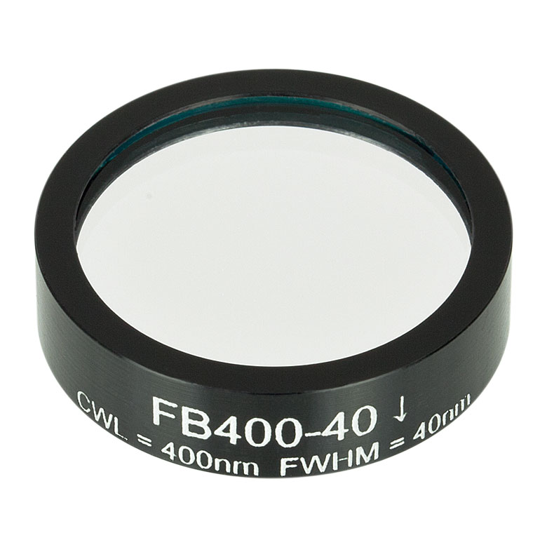
Its difference from a window or a beam splitter is precisely this selectivity. A window treats every wavelength alike and only asks not to interfere; a beam splitter divides power by direction or polarisation; a filter is the only common element that divides power by wavelength. And because it has to choose, it must lose something: no passband reaches 100%, and no stopband reaches zero.
Once that is clear, the rest of the parameters fall into place. Peak transmission, bandwidth and blocking depth pull against each other, and every filter is a compromise among the three: to be narrow, deep and highly transmitting at once costs more layers, better processes and a higher price.
2. How It Works: Four Ways of Selecting by Wavelength
Four mechanisms dominate wavelength selection, and their performance limits are quite different. Before choosing, know which one is in your hand.
- Absorptive: coloured glass, dyes or semiconductor materials absorb strongly in some bands and are relatively clear elsewhere. The simplest and cheapest, almost insensitive to angle and temperature, but all the absorbed light becomes heat, so at higher power the filter drifts, fades and eventually fractures.
- Thin-film interference: tens to hundreds of alternating high- and low-index dielectric layers make the target wavelength add in phase and the rest cancel. The spectrum can be designed precisely, absorption is minimal and the damage threshold is high, which makes it the first choice for demanding systems, but it is sensitive to angle and temperature.
- Fabry–Pérot: essentially a resonant cavity formed by two high-reflectance stacks around a spacer, transmitting only wavelengths that satisfy the resonance condition. A single cavity gives an Airy, Lorentzian peak with limited sideband suppression; cascading two or three cavities is what produces a near-rectangular passband and deeper blocking.
- Tunable: an acousto-optic tunable filter (AOTF) writes a variable-period index grating into a crystal with sound waves, while liquid-crystal or mechanically scanned Fabry–Pérot designs change the cavity length. They tune electrically, at the cost of wider bandwidth, small aperture and high price.
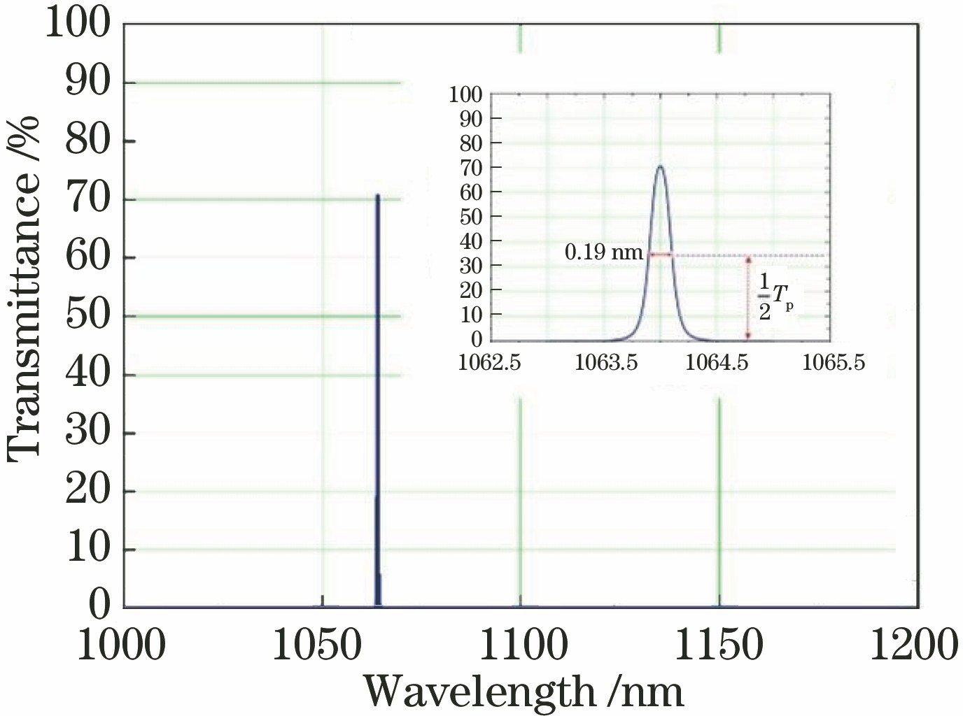
The interference structure deserves a closer look, because it sits at the heart of nearly every laser filter. A bandpass filter is basically a sandwich of reflector, spacer, reflector: the dielectric stacks on either side are highly reflective in the target band, the cavity between them lets light oscillate, and only the resonant wavelength gets through. More cavities give a squarer passband and deeper blocking, but slightly lower peak transmission and greater angle sensitivity. That is why two filters with the same headline specification can differ twofold in price.
3. Key Parameters: Reading a Filter Datasheet
A filter datasheet is the one optical specification that has to be read line by line, because the parameters are coupled: change one and the other two move. The table below lays out nine of them, with the last column telling you what happens in the system when the number is off.
| Parameter | Meaning | What goes wrong |
|---|---|---|
| Centre wavelength (CWL) | Position of the transmission peak, quoted with a manufacturing tolerance, typically ±2 nm or ±0.5% | It lands away from your source line and transmission falls off along the passband edge; for a narrowband filter, half a bandwidth of error is enough to make it useless |
| Bandwidth (FWHM) | Full width at half maximum of the peak, a measure of how narrowly it selects | Too wide and it fails to reject the neighbouring line; too narrow and it shaves the signal itself, while lowering peak transmission and worsening angle sensitivity |
| Peak transmission | Highest transmission inside the passband, including substrate absorption and back reflection | Every 1% lost is 1% of signal; in weak-light detection that 1% often sets the signal-to-noise ratio, but buying it by sacrificing blocking depth is usually a bad trade |
| Blocking depth (OD) | Suppression of the stopband at the wavelength to be rejected, OD = −log₁₀T, so OD6 means one part in a million | One OD less means ten times the leakage; in fluorescence or Raman work the leaking pump swamps the signal outright |
| Blocking range | The wavelength span over which that blocking applies, for example 200–1200 nm broadband or only one narrow segment | Quoting OD6 without a range is a classic trap: the figure may only cover 400–700 nm, so at 1064 nm you get none of that suppression |
| Passband flatness | Ripple across the top of the passband, usually given as a percentage or relative to the peak | Imaging and spectral calibration read that ripple as a false signal; the flatter the top, the more reliable the calibration |
| Acceptance angle | Range of incidence angles over which the specification still holds; interference filters are normally designed for 0° | Using it tilted brings blue shift, splits the s and p peaks and smears the passband of a converging beam, all three at once |
| Temperature coefficient | Rate at which the centre wavelength drifts with temperature, of order +0.01 nm/°C for dielectric coatings | For a 1 nm filter, a 100 °C swing is the whole passband; only a temperature-stabilised or athermal design holds it |
| Damage threshold | Limit on continuous power density or pulse energy density, quoted separately for CW and pulsed operation | The standing-wave field inside the coating makes some layers see far more intensity than the incident beam, so failure usually starts inside the stack rather than at the surface |
4. Main Types: Bandpass, Edge, Notch, Neutral Density and Tunable
Classifying by spectral curve is the most practical approach, because one glance at the curve tells you what the filter can do.
| Type | Spectral shape | Typical specification | Typical use |
|---|---|---|---|
| Bandpass | One transmission peak with stopbands on both sides | FWHM 0.1–100 nm, peak transmission 50%–95%, OD4–OD6 | Fluorescence imaging, Raman, laser line clean-up |
| Short-pass / long-pass | Transmits on one side, blocks on the other; the steeper the transition the better | Edge steepness 1%–5% of wavelength, OD4 or better | Pump and signal separation, harmonic rejection, cold mirrors |
| Notch | One narrow stopband with everything else transmitted, used to carve out a single line | Stopband 5–20 nm wide, OD6 common | Removing the Rayleigh line in Raman, laser safety eyewear |
| Neutral density | Broadband, approximately flat attenuation that reduces power without selecting wavelength | OD0.3–OD6, flatness ±5% | Switching detector ranges, coarse power setting |
| Dichroic (colour separator) | Used at 45°; reflects the short wavelengths and transmits the long ones, or the reverse | Transition 10–20 nm wide, polarisation dependent | Fluorescence filter cubes, beam combining, white-light colour splitting |
| Tunable | Centre wavelength set by voltage, sound wave or mechanical scan | Tuning range tens to hundreds of nm, bandwidth 1–10 nm | Hyperspectral imaging, wavelength scanning, spectral sensing |
5. In Depth: CWL, FWHM, OD, Angle of Incidence and Temperature
5.1 CWL and FWHM: Two Numbers That Must Be Read Together
The centre wavelength is where the peak sits, defined by the maximum transmission and quoted with a manufacturing tolerance. That tolerance matters: a filter specified at 532 nm ±2 nm may actually peak at 534 nm while your laser runs at 532 nm, and the transmission you get then depends on how steep the passband edge is, not on how handsome the nominal figure was.
The full width at half maximum is the wavelength span where transmission falls to half the peak. The usual industry bands are roughly: narrowband 0.1–10 nm, medium 10–50 nm, broadband 50–100 nm and beyond. The narrower the FWHM the more selective the filter, at the cost of lower peak transmission, greater sensitivity to angle and temperature, and a higher price.
So how narrow should it be? Match the spectral width of your signal. A laser linewidth is usually far below 0.1 nm, so a narrowband filter chosen as laser wavelength plus tolerance is enough; a fluorescence emission band is tens of nanometres wide, and forcing a 1 nm filter on it only throws most of the signal away. The test is simple: the passband must cover the signal and must not cover the nearest interfering line.
5.2 Blocking Depth and OD
Blocking depth measures how hard the stopband suppresses, expressed as optical density:
OD = −log₁₀(Tblock), where Tblock is the transmission in the stopband.
| OD value | Stopband transmission | Suppression | Leakage from 1 W incident |
|---|---|---|---|
| OD2 | 1% | 99% | 10 mW |
| OD3 | 0.1% | 99.9% | 1 mW |
| OD4 | 0.01% | 99.99% | 100 μW |
| OD5 | 0.001% | 99.999% | 10 μW |
| OD6 | 0.0001% | 99.9999% | 1 μW |
Fluorescence detection is where OD is pushed hardest. The excitation is six to nine orders of magnitude stronger than the fluorescence, so an emission filter of only OD3 lets enough excitation through to bury the signal completely. Fluorescence cubes therefore usually demand OD5 or better on both the excitation and the emission filter, and across the whole stopband rather than at one nominal wavelength.
One question has to be asked of every supplier: over what range is that OD6 achieved? The reflection band of a dielectric stack is typically 30%–40% of the centre wavelength, so covering 200–1200 nm means stacking several groups of layers. An OD figure with no range is almost meaningless, and filters claiming OD6 that actually cover only 500–600 nm are not rare.
5.3 Angle of Incidence: A Small Tilt Shifts It Blue
The most easily overlooked property of an interference filter is that the transmission peak moves with angle. At oblique incidence the effective optical path inside the layers shortens, the resonant wavelength drops, and the peak shifts towards the blue. The approximation is:
λ(θ) ≈ λ₀ · √(neff² − sin²θ) / neff
where λ₀ is the centre wavelength at normal incidence, θ the angle of incidence and neff the effective index of the coating, usually 1.5–2.0. Put in some numbers: with neff = 1.8 and θ = 10° the shift is about 0.5%, which at 550 nm is roughly 2.6 nm; at 15° it is about 1%, or 5.7 nm. For a filter with a 1 nm FWHM that is the entire passband walking away.
💡 Engineering note: Besides the blue shift, oblique incidence separates the s- and p-polarised transmission peaks: their CWL and FWHM both differ, which shows up as transmission jumping with polarisation state in a polarisation-sensitive path. A converging or diverging beam, such as light after a focusing lens or straight out of an uncollimated diode, contains a range of angles, and the effect is a smeared, lowered passband. Interference filters therefore belong in collimated light and as close to normal incidence as possible; if you must tilt, re-specify the centre wavelength for the actual angle.
5.4 Thermal Drift
Temperature also moves the centre wavelength: thermal expansion thickens the layers while the refractive indices change with temperature, and the two together shift the wavelength red as it gets hotter. Conventional dielectric filters run at about +0.01 nm/°C.
That sounds negligible until it is read against the bandwidth. For a 1 nm filter a 100 °C swing drifts a whole passband; for a 40 nm filter the same drift is 2.5% and barely noticeable. So whether thermal drift matters has no universal answer: it depends on how narrow the FWHM is and how far the operating temperature sits from the calibration temperature.
Where more stability is needed there are two routes: specify an athermal design, which combines two materials with opposing thermo-optic coefficients so the drifts cancel, or put the filter mount under active temperature control. The first is simpler but expensive, the second is flexible but costs space and power.
6. Applications: Where Filters Are Used
Filters all do the same thing: separate signal from everything else in the spectral domain. The reasons differ, the action does not.
- Fluorescence microscopy and imaging: the excitation filter selects the pump, the dichroic reflects it onto the sample and transmits the fluorescence, and the emission filter suppresses what is left of the pump. Three filters form one cube, and if any one of them lacks OD the contrast of the whole set collapses.
- Laser systems: intra-cavity or extra-cavity wavelength selection, amplified spontaneous emission suppression between stages, and harmonic separation, for instance picking the residual 1064 nm out of 532 nm. High-power work needs laser-grade hard coatings and a peak power density calculation.
- Raman and spectral analysis: a notch or long-pass filter suppresses the Rayleigh scattering by seven orders of magnitude, which is the only way the Raman lines a few wavenumbers away become visible. This is one of the most demanding OD applications there is.
- Optical communications and WDM: DWDM uses very narrow filters, 0.1–0.8 nm, to separate adjacent channels; the tighter the channel spacing, the harsher the demands on CWL tolerance and thermal drift.
- Laser safety: the core of a pair of laser goggles is one or more filters with high OD at the laser wavelength and high transmission in the visible; multi-wavelength workplaces need several stopbands stacked.
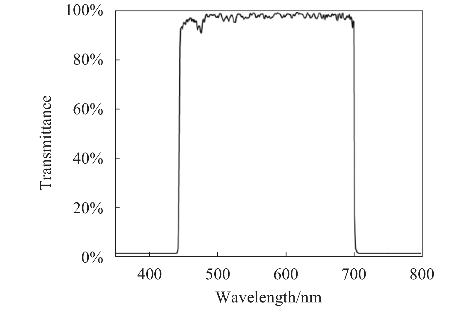
- Imaging and photography: an infrared-cut filter passes visible light and removes the haze beyond 700 nm, while the narrowband filters used in astronomy and machine vision do the opposite, keeping one line and suppressing sky background and light pollution.
7. Common Myths: Six Widespread Misunderstandings
Filters have few parameters and they are coupled, so the misconceptions cluster around one question: which number matters most.
Myth 1: The higher the peak transmission the better
High transmission is usually bought with fewer cavities and a thinner stack, and the price is shallower blocking and a rounder passband. For most applications OD matters more than peak transmission: a weak signal can be recovered with longer integration, a background that will not go down cannot. Anything above 90% is already good, and the last few points are substrate absorption and back reflection.
Myth 2: Filters are insensitive to angle
Absorptive filters are, interference filters very much are not. The centre wavelength shifts blue as √(1−(sinθ/neff)²), which is several nanometres at 10°; oblique incidence also splits the s and p peaks, and a converging beam smears the passband as a whole.
Myth 3: A filter is only there to throw light away
The rejected light is often the useful light. A dichroic reflects the short wavelengths to excite and transmits the long ones to image, and both paths are working; colour combining, fluorescence splitting and cold mirrors follow the same idea. Treating a filter as a consumable throws away half the energy.
Myth 4: A higher OD means better transmission
The opposite. OD describes how hard the stopband suppresses, so a higher OD means a darker stopband; how much the passband transmits is a different parameter, the peak transmission, and the two are not directly related. Reading OD as transmitting power reverses the whole selection.
Myth 5: Every filter can take high power
It cannot. Absorptive coloured glass works by absorption and will heat, drift and finally fracture; dielectric filters take far more but still have a limit, and the standing-wave field inside the stack drives some layers well above the incident intensity, so failure often starts inside the coating. High power demands laser-grade hard coatings.
Myth 6: The narrower the bandwidth the better
Bandwidth has to match the signal. Narrowing until it shaves the signal itself trades transmission for purity at a loss, and narrower filters have lower peaks, worse angle and temperature sensitivity and higher prices. Measure the gap between your signal and the nearest interfering line, then fit the passband between them.
◆ Recommended Reading
- What Is a Fabry–Pérot Resonator? Finesse, Free Spectral Range and Resolving Power
- What Is an Optical Window? The Transparent Door of a Laser System
- Optical Glass and Window Materials: Principles, Classification, Parameters and 6 Common Misconceptions
- What Is a Beam Splitter? How One Beam Becomes Two
Leave a Reply